Clutch control device for four-wheel drive vehicle

a technology of clutch control device and four-wheel drive vehicle, which is applied in the direction of clutch, control device, vehicle components, etc., can solve the problems of inability to complete the switch to the four-wheel drive mode, inability to obtain sufficient travel stability, and inability to complete the switch. achieve the effect of reducing the transmission torque of the friction clutch, and reducing the distribution of drive force to the auxiliary drive wheels

Active Publication Date: 2017-06-29
NISSAN MOTOR CO LTD
View PDF2 Cites 8 Cited by
  • Summary
  • Abstract
  • Description
  • Claims
  • Application Information

AI Technical Summary

Benefits of technology

[0009]In the clutch control device for a four-wheel drive vehicle of the present invention, when engaging a dog clutch, the clutch control unit engages the dog clutch after engaging a friction clutch and synchronizing the dog clutch. Then, at the time of this engagement of the dog clutch, if an engagement standby state is detected in which the engagement is incomplete due to an impact of a meshing portion such as the teeth, the clutch control device reduces the transmission torque of the friction clutch. By reducing the transmission torque of the friction clutch, the distribution of drive force to the auxiliary drive wheels is reduced and a differential rotation is generated between the drive source side and the auxiliary drive wheel-side of the dog clutch; therefore, the meshing portions such as the teeth are moved relative to each other, allowing the engagement of the dog clutch to be completed. In this manner, in the present invention, even if the state becomes an engagement standby state when engaging the dog clutch, in which the engagement is incomplete due to an impact of a meshing portion, or the like, it is possible to generate a differential rotation in the dog clutch in order to reliably realize an engagement.

Problems solved by technology

However, when the dog clutch is synchronized, there are cases in which the teeth of the engagement member on the drive source side and the teeth of the engagement member on the auxiliary drive wheel-side strike each other, and synchronous rotation takes place in an engagement standby state in which an engagement is not made.
In this case, the wait state is maintained until a differential rotation occurs between the main drive wheel-side and the auxiliary drive wheel-side of the dog clutch, and a switching of the drive mode cannot be completed.
Therefore, if the dog clutch is maintained in an engagement standby state when attempting to switch the drive mode to a four-wheel drive mode in order to increase travel stability, there is also the risk that a switch to the four-wheel drive mode is not made, and that sufficient travel stability cannot be obtained during that time.
Then, at the time of this engagement of the dog clutch, if an engagement standby state is detected in which the engagement is incomplete due to an impact of a meshing portion such as the teeth, the clutch control device reduces the transmission torque of the friction clutch.

Method used


Image

  • Clutch control device for four-wheel drive vehicle
  • Clutch control device for four-wheel drive vehicle
  • Clutch control device for four-wheel drive vehicle

Examples


first embodiment

[0023]Referring initially to FIG. 1, a front wheel drive based four-wheel drive vehicle (one example of a four-wheel drive vehicle) is schematically illustrated with a clutch control device in accordance with a first embodiment.

Drive System Configuration of the Four-Wheel Drive Vehicle

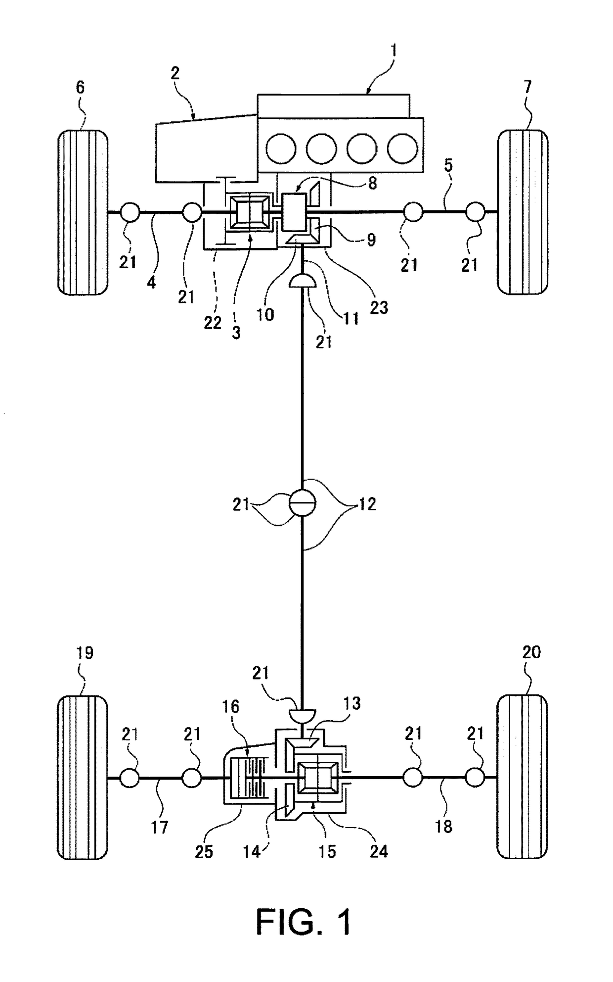
[0024]FIG. 1 illustrates the configuration of the drive system of a front wheel drive based four-wheel drive vehicle to which is applied the clutch control device of the first embodiment. The drive system configuration of the four-wheel drive vehicle will be described below based on FIG. 1.

[0025]The front wheel drive system of the four-wheel drive vehicle is provided with a transverse engine 1 (drive source), a transmission 2, a front differential 3, a left front wheel drive shaft 4, a right front wheel drive shaft 5, a left front wheel 6 (main drive wheel), and a right front wheel 7 (main drive wheel), as illustrated in FIG. 1. That is, the drive force is transmitted from the transverse engine 1 and t...

second embodiment

[0094]The second embodiment is an embodiment in which, when reducing the transmission torque of the electronically controlled coupling 16 in an engagement standby state during deceleration, the reduction is carried out gradually over time. That is, in FIG. 8, when reducing the engagement command output TETS from time t85, the reduction is carried out at a predetermined decrease gradient, as indicated by the dotted line in the drawing. In this case, the decrease gradient may be constant or variable in accordance with the deceleration degree. If variable, the decrease gradient may be made gradual when the deceleration degree is high in order to suppress engagement shock. Or, conversely, the decrease gradient may be made steep in order to increase responsiveness when the deceleration degree is large; the decrease gradient may be appropriately set according to the vehicle characteristics or the set speed of the vehicle speed threshold value VSPst.

[0095]2-1) In the clutch control device ...

third embodiment

[0096]The third embodiment is an embodiment in which, when carrying out a drive mode switch control that releases the dog clutch 8 when an engagement standby state is detected, the release is carried out without releasing the electronically controlled coupling 16 in advance.

[0097]As illustrated in the flowchart of FIG. 9, in S301 to which the process proceeds when an engagement standby state is determined in Step S101, it is determined whether or not to transition to the disconnected two-wheel drive mode in which the dog clutch 8 is released by a transition of the vehicle state. If shifting to the disconnected two-wheel drive mode, the process proceeds to Step S302, and if not shifting to the disconnected two-wheel drive mode, the process proceeds to Step S102 and the same process as in the first embodiment is carried out.

[0098]In Step S302, to which the process proceeds when transitioning to the disconnected two-wheel drive mode, the dog clutch 8 and the electronically controlled c...


PUM


Abstract

A clutch control device is provided for a four-wheel drive vehicle for transmitting drive force to the rear wheels. The clutch control device includes a dog clutch and a friction clutch, and a 4WD control unit that controls the engagement and disengagement of the dog clutch and the friction clutch. The 4WD control unit is switchable between a two-wheel drive mode and a four-wheel drive mode. The 4WD control unit is programmed to control engagement of the dog clutch so that the dog clutch is engaged after the friction clutch is engaged and the dog clutch is synchronized. During engagement of the dog clutch, the 4WD control unit is programmed to reduce a transmission torque of the friction clutch when the dog clutch engagement standby state is detected.

Description

CROSS-REFERENCE TO RELATED APPLICATIONS[0001]This application is a U.S. National stage application of International Application No. PCT / JP2015 / 055248, filed Feb. 24, 2015, which claims priority to JP Patent Application No. 2014-038482 filed on Feb. 28, 2014, and JP Patent Application No. 2014-038483 filed on Feb. 28, 2014, the contents of which are hereby incorporated herein by reference.BACKGROUND[0002]Field of the Invention[0003]The present invention generally relates to a clutch control device for a four-wheel drive vehicle in which a system for transmitting drive force to auxiliary drive wheels is provided with a dog clutch and a friction clutch.[0004]Background Information[0005]Conventionally, a front wheel drive based four-wheel drive vehicle in which a system for transmitting drive force to the rear wheels is provided with a dog clutch and a friction clutch is known (refer to, for example, Japanese Laid-Open Patent Application No. 2010-254058). In this four-wheel drive vehicl...

Claims


Application Information

Patent Timeline
Patent Type & Authority Applications(United States)
IPC IPC(8): B60K23/08F16D13/00B60K17/344F16D48/06B60K17/02F16D11/00F16D21/00
CPCB60K23/08F16D11/00F16D13/00F16D21/00F16D48/06B60K17/02B60K2023/0858F16D2500/10431F16D2500/1045F16D2500/10462F16D2500/3108F16D2500/3144F16D2500/5122B60K17/344B60K2023/0825B60K2023/0833
Inventor OGAWA, KATSUYOSHIMORI, ATSUHIROMITSUISHI, SHUNICHIMORITA, MAKOTOTAKAISHI, TETSU
Owner NISSAN MOTOR CO LTD
Why Eureka
Try Eureka