Sensor

a technology of sensors and sensors, applied in the field of sensors, can solve problems such as increasing complexity in the design of systems and signal processing

Inactive Publication Date: 2017-06-29
EPCOS AG
View PDF8 Cites 6 Cited by
  • Summary
  • Abstract
  • Description
  • Claims
  • Application Information

AI Technical Summary

Benefits of technology

[0005]Embodiments of the invention provide an improved sensor

Problems solved by technology

If these sensors have signal conversion principles which differ from one another, th

Method used


Image

  • Sensor
  • Sensor
  • Sensor

Examples


Embodiment Construction

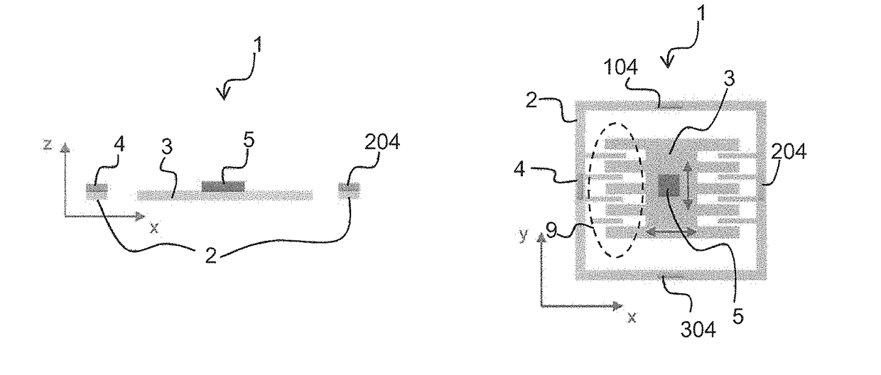
[0052]FIG. 1 shows a sensor 1. The sensor 1 has a fixed structure 2 and a movable structure 3 which can move relative to the fixed structure 2.

[0053]The sensor 1 is configured to measure a movement of the movable structure 3 relative to the fixed structure 2. This sensor concept is used, for example, in pressure sensors in which the deflection of a diaphragm relative to a frame is measured. Accordingly, the movable structure 3 may be the diaphragm, and the fixed structure 2 may be the frame. Other sensors, for example, sensors for measuring accelerations or sensors for measuring rates of rotation, are also based on the measurement of the deflection of a movable structure 3 relative to a fixed structure 2. The movable structure 3 may be a seismic mass.

[0054]In the exemplary embodiment illustrated in FIG. 1, the movable structure 3 is a diaphragm. Furthermore, the fixed structure 2 is a frame.

[0055]The sensor 1 shown in FIG. 1 is an inertial sensor for measuring accelerations. The mov...


PUM


Abstract

A sensor is disclosed. In an embodiment, the sensor includes a fixed structure, a movable structure movable relative to the fixed structure, a magnet configured to generate a magnetic field and a first magnetically sensitive element configured to determine the magnetic field at a position of the first magnetically sensitive element. The magnet is fastened to the fixed structure and the first magnetically sensitive element is fastened to the movable structure. Alternatively, the magnet is fastened to the movable structure and the first magnetically sensitive element is fastened to the fixed structure.

Description

[0001]This patent application is a national phase filing under section 371 of PCT / EP2015 / 065358, filed Jul. 6, 2015, which claims the priority of German patent application 10 2014 109 701.7, filed Jul. 10, 2014, each of which is incorporated herein by reference in its entirety.TECHNICAL FIELD[0002]The present invention relates to a sensor. The sensor may be, in particular, a sensor in which a measurement variable is determined on the basis of a deflection of a movable structure in relation to a fixed structure. A measurement principle of this kind is used, for example, in motion sensors, pressure sensors or rate of rotation sensors.BACKGROUND[0003]In many applications, sensors for measuring different sensor variables are combined with one another, for example, in inertial sensors, which determine three to six degrees of freedom (DOF), and in motion sensors, which determine six to ten degrees of freedom. If these sensors have signal conversion principles which differ from one another...

Claims


Application Information

Patent Timeline
IPC IPC(8): G01R33/00G01R33/09G01R33/038
CPCG01R33/0005G01R33/093G01R33/038G01R33/0047G01L1/122G01L9/007G01L9/14G01L19/06G01L5/164G01C19/5719G01P15/105
Inventor OSTRICK, BERNHARDSCHREIBER-PRILLWITZ, WOLFGANG
Owner EPCOS AG
Why Eureka
Try Eureka