This helps you quickly interpret patents by identifying the three key elements:
Problems solved by technology
Method used
Benefits of technology
Benefits of technology
The invention provides a refrigerant system for conditioning air and items in a human-occupied dwelling. The system has two heat transfer circuits, one located outside the house and one inside the house. The first circuit uses a refrigerant with low flammability and toxicity, while the second circuit uses a different refrigerant with lower flammability. The system also has an intermediate heat exchanger that allows heat transfer between the two refrigerants. The use of low-GWP refrigerants and the selection of appropriate refrigerants reduces the environmental impact of the system.
Problems solved by technology
Accordingly, the preferred configurations and selection of refrigerants permit the provision of systems which benefit from the use of refrigerants that have many desirable properties, such as capacity, efficiency, low GWP and low ODP, but at the same time, possess one or more properties which would otherwise make them highly disadvantageous and / or preclude their use in proximity to the humans or other animals in a confined and / or closed location.
Method used
Image
Click on the blue label to locate the original text in one second.
Reading with bidirectional positioning of images and text.
Examples
example 1a
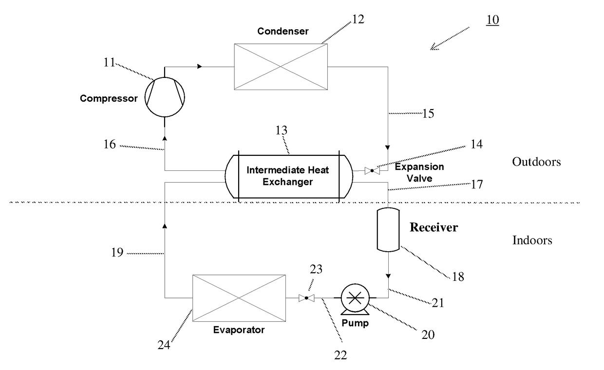
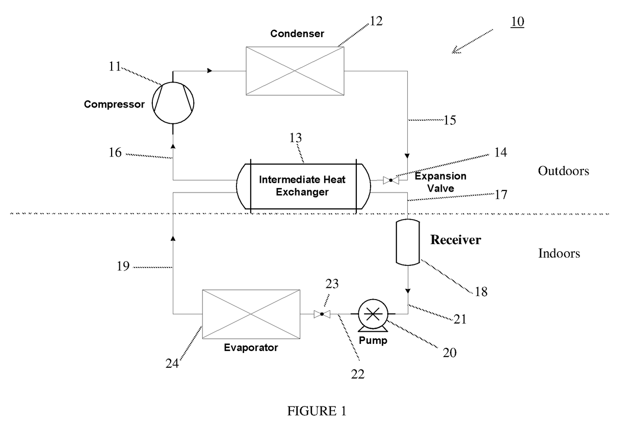
[0063]Example 1A (FIG. 1) Operating Conditions
[0064]A system configured as illustrated herein in FIG. 1 is operated according to the following operating parameters using a series of different first (outdoor) and second (indoor) refrigerants:
[0065]1. Condensing temperature=45° C., corresponding outdoor ambient temperature=35° C.
[0066]2. Condensing Temperature- Ambient Temperature=10° C.
[0067]3. Expansion device sub-cooling=5.0° C.
[0068]4. Evaporating temperature=7° C., corresponding indoor room temperature=27° C.
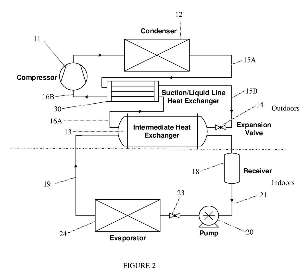
[0079]A system configured as illustrated herein in FIG. 2 is operated according to the following operating parameters using a series of different first (outdoor) and second (indoor) refrigerants:
[0080]1. Condensing temperature=45° C., corresponding outdoor ambient temperature=35° C.
[0081]2. Condensing Temperature—Ambient Temperature=10° C.
[0082]3. Expansion device sub-cooling=5.0° C.
[0083]4. Evaporating temperature=7°C., corresponding indoor room temperature=27° C.
[0089]Example 2B (FIG. 2)—Alteration of Condenser Temperature
[0090]A system configured as illustrated herein in FIG. 2 is operated according to the same operating parameters as Example 2A using a series of different first (outdoor) and second (indoor) refrigerants, except that the condensing temperature is adjusted for each blend in order to obtain an efficiency that substantially matches the efficiency achieved according to Comparative Example 1. The results are provided in Table 2B below:
PUM
Abstract
Disclosed are refrigerant systems for conditioning air and / or items located within a dwelling occupied by humans or other animals preferably including at least a first heat transfer circuit containing a first heat transfer fluid in a vapor / compression circulation loop located substantially outside of the dwelling and at least a second heat transfer circuit, which contains a second heat transfer fluid different than the first heat transfer fluid, located substantially inside of the dwelling. In preferred embodiments, the second heat transfer circuit does not include a vapor compressor, but the system includes at least one intermediate heat exchanger which permits exchange of heat between the first heat transfer fluid and the second heat transfer fluid such that heat is transferred to the first heat transfer fluid, preferably thereby evaporating the first heat transfer fluid, and from the second heat transfer fluid, thereby condensing the second heat transfer fluid. Preferably, the intermediate heat exchanger is located outside the dwelling. The first heat transfer fluid comprises a refrigerant which has a GWP of not greater than about 500 and that the second heat transfer fluid comprises a refrigerant that also has a GWP of less than 500 and which has a low flammability and a low toxicity, and even more preferably a flammability that is substantially less than the flammability of the refrigerant in the first heat transfer fluid and / or a toxicity that is substantially less than the toxicity of the refrigerant in said first heat transfer fluid.
Description
CROSS-REFERENCE TO RELATED APPLICATIONS[0001]The present application claims priority to U.S. Provisional Application No. 62 / 295,731, filed Feb. 16, 2016, and is a continuation-in-part of U.S. application Ser. No. 15 / 400,891, filed Jan. 6, 2017 which application claims priority to U.S. Provisional Application No. 62 / 275,382, filed Jan. 6, 2016 the entire contents of which is hereby incorporated by reference.FIELD OF THE INVENTION[0002]The present invention relates to high efficiency, low-global warming potential (“low GWP”) air conditioning and related refrigeration systems and methods that are safe and effective.BACKGROUND[0003]In a typical air conditioning and refrigerant systems, a compressor is used to compress a heat transfer vapor from a lower to a higher pressure, which in turn adds heat to the vapor. This added heat is typically rejected in a heat exchanger, commonly referred to as a condenser. In the condenser the vapor, at least in major proportion, is condensed to produce ...
Claims
Application Information
Patent Timeline
Application Date:The date an application was filed.
Publication Date:The date a patent or application was officially published.
First Publication Date:The earliest publication date of a patent with the same application number.
Issue Date:Publication date of the patent grant document.
PCT Entry Date:The Entry date of PCT National Phase.
Estimated Expiry Date:The statutory expiry date of a patent right according to the Patent Law, and it is the longest term of protection that the patent right can achieve without the termination of the patent right due to other reasons(Term extension factor has been taken into account ).
Invalid Date:Actual expiry date is based on effective date or publication date of legal transaction data of invalid patent.

