
Deterent for unmanned aerial systems

a technology detection devices, applied in direction/deviation determining electromagnetic systems, instruments, and using reradiation, etc., can solve problems such as significant hazards for commercial and general use, and intentional use of unmanned aerial systems to violate privacy

Active Publication Date: 2017-07-06
XIDRONE SYST INC
View PDF0 Cites 109 Cited by
  • Summary
  • Abstract
  • Description
  • Claims
  • Application Information

AI Technical Summary

Benefits of technology

The patent text describes a system and method for detecting, tracking, identifying, and interdicting small unmanned aerial systems (sUAS), such as drones, to protect critical infrastructure and prevent them from being used for invading privacy or carrying out terrorist and criminal activities. The system uses a combination of sensors and a sensor fusion processor to analyze the output of these sensors and determine the level of threat assessment. If the threat assessment level exceeds a certain threshold, the system automatically deploys interdiction to incapacitate or destroy the sUAS. The technical effect of this patent is to provide a reliable and integrated solution for detecting and interdicting sUAS in a way that can protect critical infrastructure and prevent them from being used for harm.

Problems solved by technology

While there may be many safe commercial and recreational uses for unmanned aerial systems, recent publicized events tell us that significant hazards exist to commercial and general aviation, public, private and government interests even if a UAS is operated without malicious intent.
Furthermore, unmanned aerial systems have been used intentionally to violate the privacy of personal, commercial, educational, athletic, entertainment and governmental activities.
An unintended consequence of off-the-shelf (OTS) commercially available unmanned aerial systems is the capability to be used in the furtherance of invading privacy, or carrying out terrorist and / or criminal activities.

Method used


Image

  • Deterent for unmanned aerial systems
  • Deterent for unmanned aerial systems
  • Deterent for unmanned aerial systems

Examples


Embodiment Construction

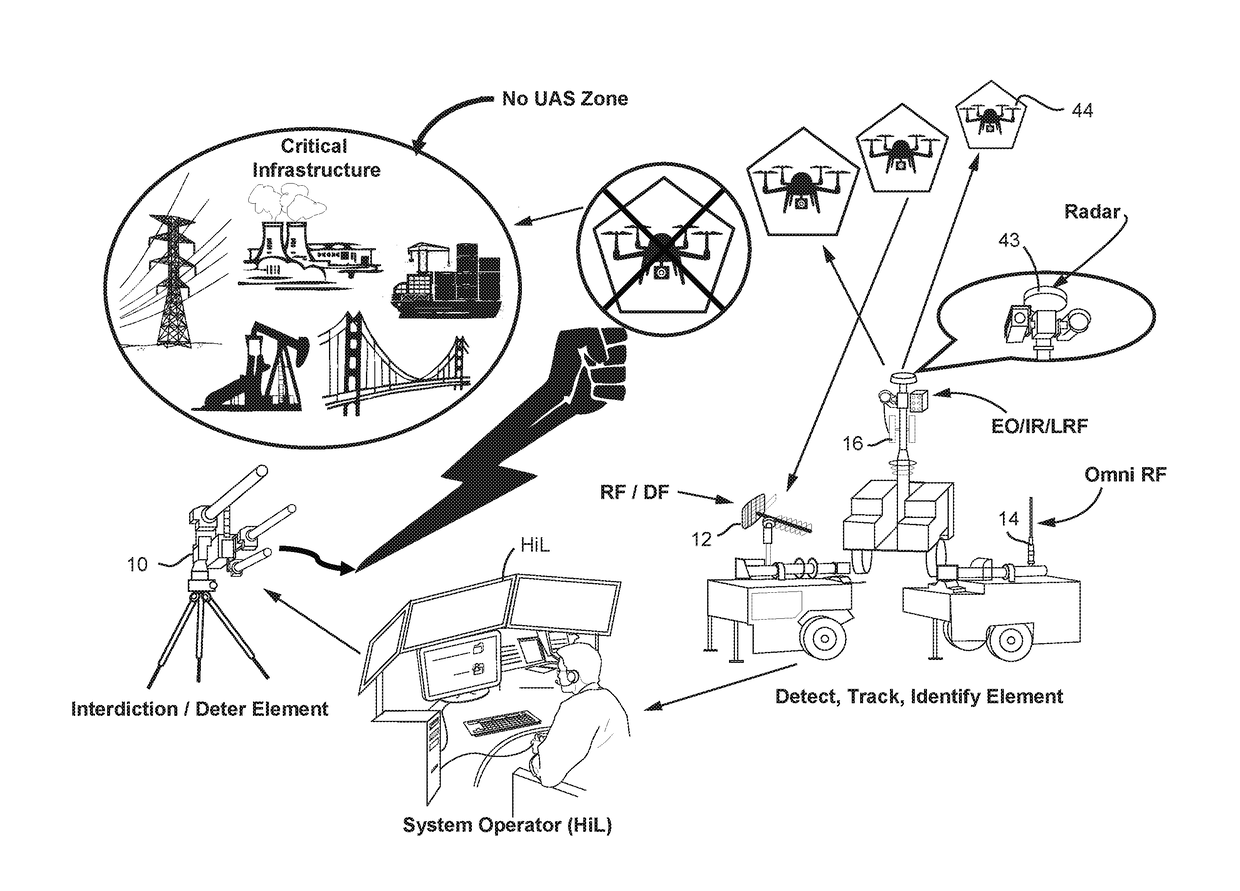
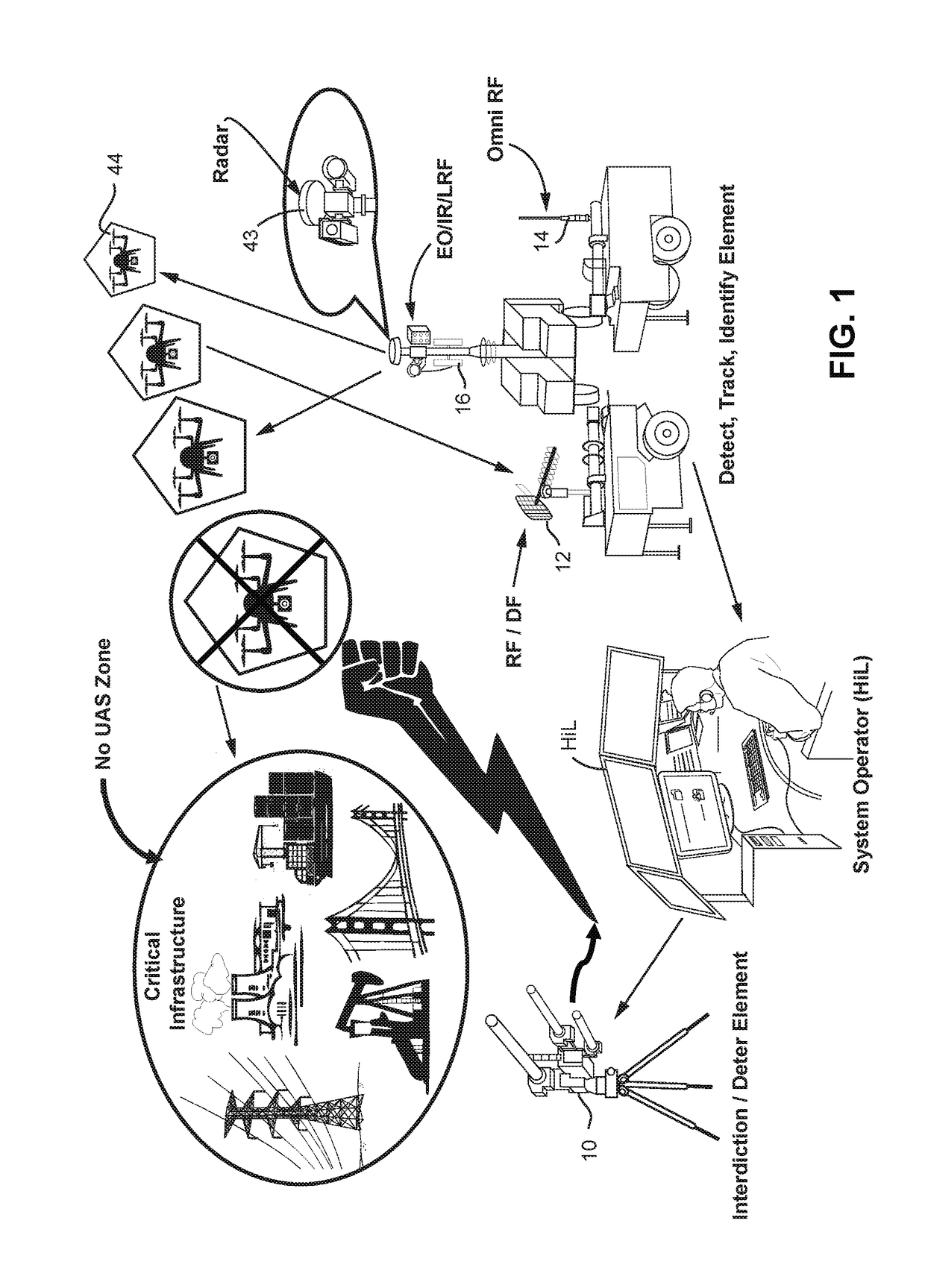
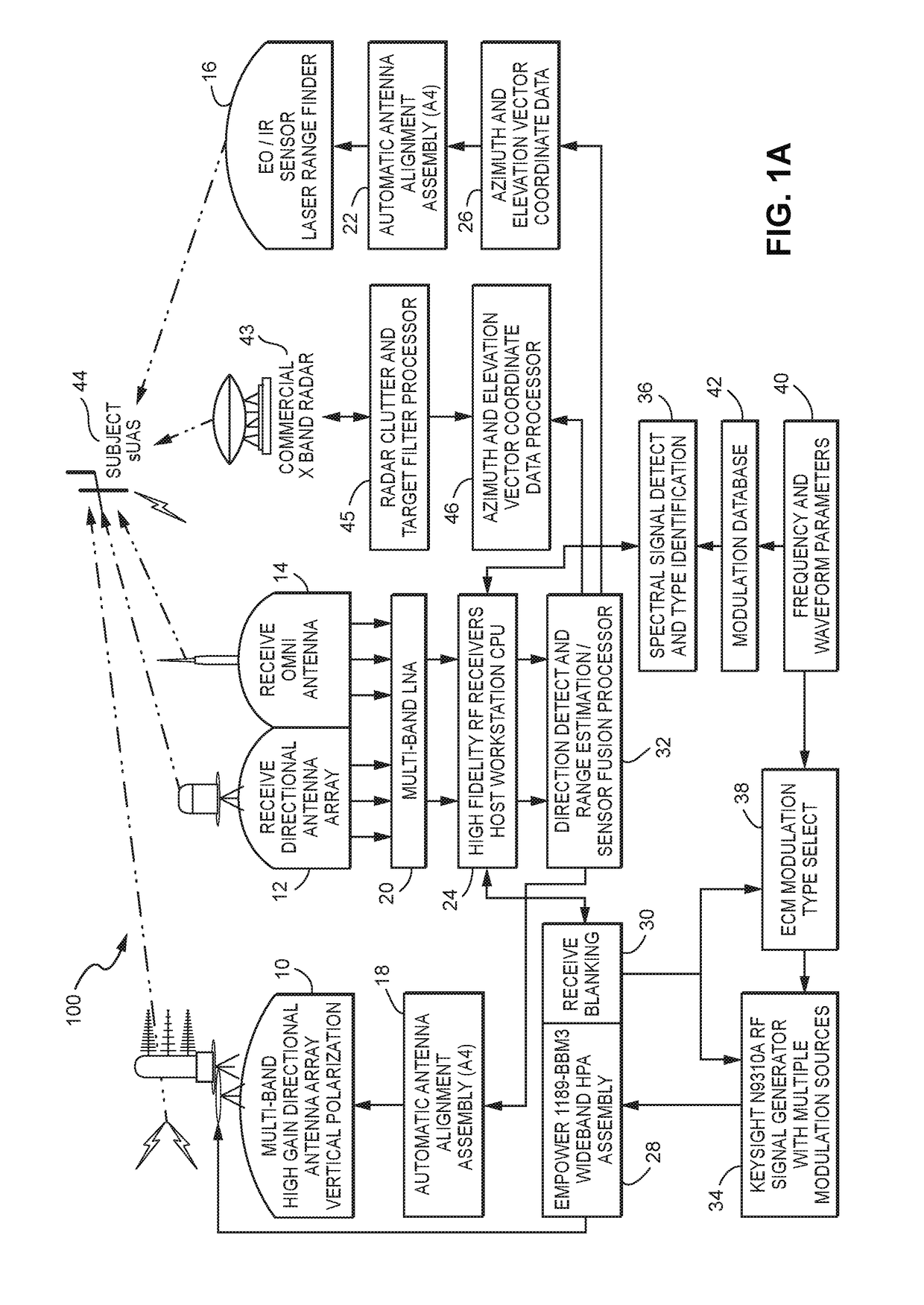
[0012]FIG. 1 shows an example non-limiting system for detecting, tracking, classifying and interdicting a UAS such as a drone 44. In the example shown, several different sensors using different technologies are used to detect the target 44. Such sensors include, in one non-limiting embodiment, a commercial ground based radar 43; an optical and / or infrared and / or laser range finder 16; an omnidirectional radio frequency (RF) receiving antenna 14; and a directional radio frequency (RF) receiving / direction finding antenna 12. Such equipment can be mounted on separate fixtures such as mobile trailers, or on the same fixture or other structure. The outputs of these sensors are analyzed using a sensor fusion processor (described below) to detect and classify the target 44, and to determine a level of threat assessment. In some non-limiting embodiments, a human can be in the loop (HiL or “human in the loop”) to render judgment; in other scenarios the system is entirely automatic. If the th...


PUM


Abstract

A system (100) for providing an integrated multi-sensor detection and countermeasure against commercial unmanned aerial systems / vehicles (44) and includes a detecting element (103, 104, 105), a tracking element (103,104, 105) an identification element (103, 104, 105) and an interdiction element (102). The detecting element detects an unmanned aerial vehicle in flight in the region of, or approaching, a property, place, event or very important person. The tracking element determines the exact location of the unmanned aerial vehicle. The identification / classification element utilizing data from the other elements generates the identification and threat assessment of the UAS. The interdiction element, based on automated algorithms can either direct the unmanned aerial vehicle away from the property, place, event or very important person in a non-destructive manner, or can disable the unmanned aerial vehicle in a destructive manner. The interdiction process may be over ridden by intervention by a System Operator / HiL.

Description

CROSS-REFERENCE TO RELATED APPLICATIONS[0001]This application is a continuation-in-part of U.S. patent application Ser. No. 14 / 821,907 filed Aug. 10, 2015; which claims benefit of U.S. Provisional Application No. 62 / 094,154 filed Dec. 19, 2014. The disclosures of these prior applications are incorporated herein in their entirety by reference.STATEMENT REGARDING FEDERALLY SPONSORED RESEARCH OR DEVELOPMENT[0002]None.FIELD[0003]The technology herein relates to reliable detection and interdiction of unmanned aerial systems such as drones.BACKGROUND AND SUMMARY[0004]Small Unmanned Aerial Systems (sUAS), weighing less than 20 kg or 55 pounds, which are commonly referred to as “drones”, are commercially available to the general public. Drone—designated as 44 in FIG. 1A, thus refers to an unmanned aircraft or ship guided by remote control or onboard computers, allowing for human correction (i.e., semi-autonomous), or autonomous, see also UAV, UAS, sUAS, RPA. While there may be many safe com...

Claims


Application Information

Patent Timeline
Patent Type & Authority Applications(United States)
IPC IPC(8): G01S7/38G01S13/66F41H11/02G01S13/86G01S13/933
CPCG01S7/38G01S13/86G01S13/66F41H11/02G01S7/021F41H13/0075G01S13/91G01S13/883G01S13/88G01S13/9303G01S3/782G01S7/414G01S13/42H04K3/45H04K3/65H04K3/92H04K2203/22H04K3/44H04K3/42H04K2203/14G08G5/0082G08G5/006G08G5/0069G08G5/0026G01S13/933
Inventor PARKER, DWAINE A.STERN, DAMON E.PIERCE, LAWRENCE S.
Owner XIDRONE SYST INC
Learn More