Flow mixers for respiratory therapy systems

a flow mixer and respiratory therapy technology, applied in the field of respiratory therapy systems, can solve the problems of inability to the inability to accurately determine the characteristic of gases flowing through the passageway, and the inability to accurately predict the magnitude of errors in the output signal of the sensor used, so as to improve the uniformity of the flow, and improve the accuracy of the sensor

Active Publication Date: 2017-07-13
FISHER & PAYKEL HEALTHCARE LTD
View PDF30 Cites 17 Cited by
  • Summary
  • Abstract
  • Description
  • Claims
  • Application Information

AI Technical Summary

Benefits of technology

[0007]Certain features, aspects, and advantages of at least one of the embodiments disclosed herein include the realization that mixing gases flowing through a gases passageway upstream of a sensor configured to measure of a characteristic of the gases can improve the accuracy of the sensor by improving uniformity in the flow along a cross-section or profile of the gases passageway. “Mixing” as used herein may be understood to refer to redistributing or conditioning a flow of gases that has been asymmetrically split along a first cross-section of a gases passageway into, for example, high-velocity components and low-velocity components, such that the velocity of the flow of gases after mixing may be more symmetric along a second cross-section of the gases passageway downstream of the first cross-section (as shown and described in FIG. 7 and elsewhere in this disclosure). The flow of gases may be mixed or made more homogenous to improve the accuracy of a sensor by positioning a static mixer or other mixing apparatus in the gases passageway upstream of the sensor, such that the mixer imparts a tangential, helical, swirling, or rotary motion to the flow of gases,

Problems solved by technology

In some cases, the accuracy or precision of a sensor used to determine a characteristic of gases flowing through a gases passageway can be less than desirable if the characteristic occurs in a radially asymmetric pattern across a cross-section or profile of the gases passageway.
For example, if gases flow through a gases passageway that comprises a bend, the velocity of the gases in the gases passageway can be radially asymmetric in a cross-section of the gases passageway at or near the bend or downstream of the bend, This variability of a given gases characteristic can undesirably affect the sensor accuracy, particularly if the number and severity of bends in the gases passageway in use will be unknown, as the magnitude of errors in output signals of the sensor used can be difficult to predict.
Similarly, non-laminar flow (that is, turbulent flow) also can adversely impact the accuracy or precision of the reading from the sensor.

Method used


Image

  • Flow mixers for respiratory therapy systems
  • Flow mixers for respiratory therapy systems
  • Flow mixers for respiratory therapy systems

Examples


Embodiment Construction

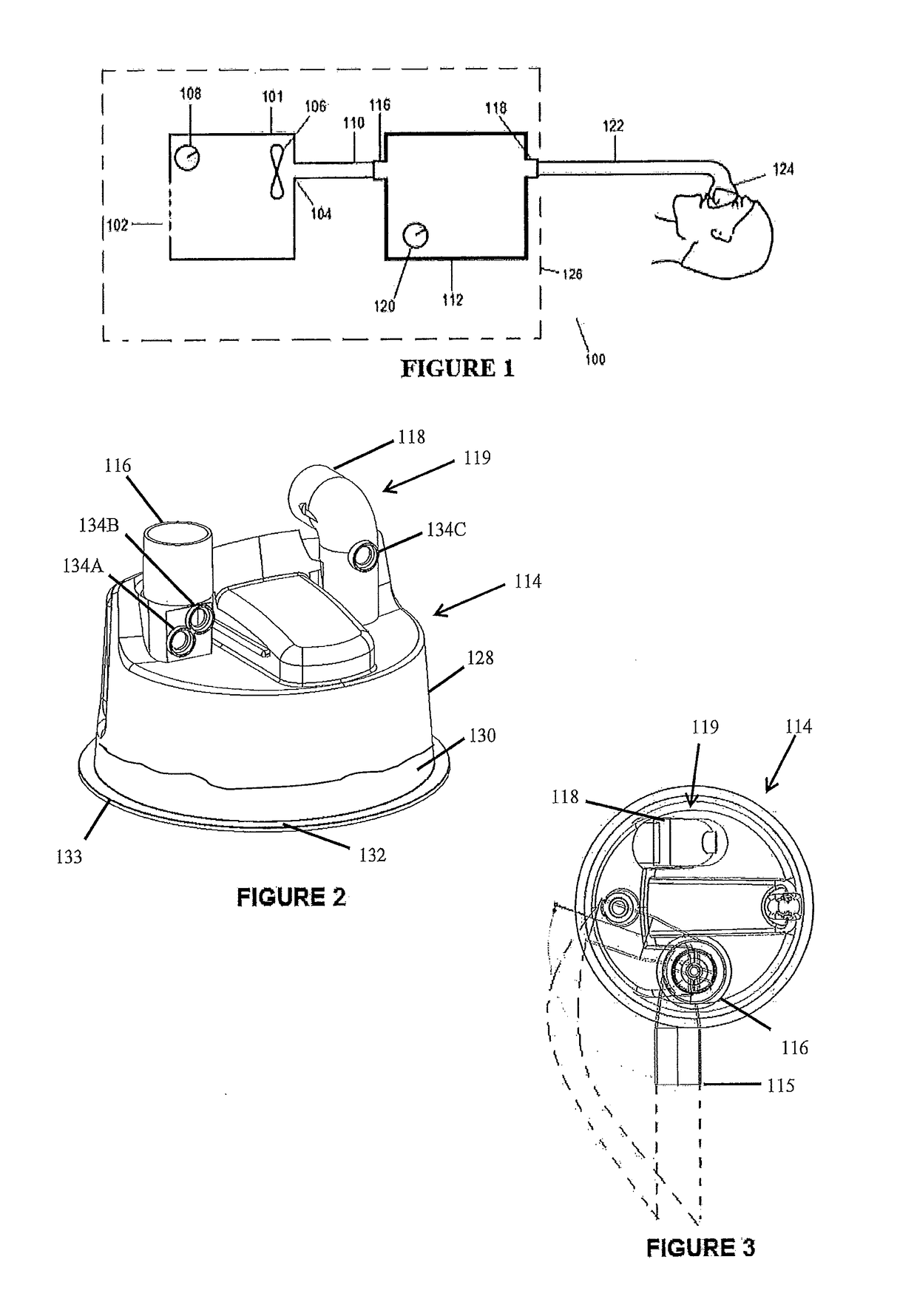
[0043]FIG. 1 shows a schematic diagram of an example configuration for a respiratory therapy system 100, In the illustrated configuration, the respiratory therapy system 100 may comprise a flow generator 101. The flow generator 101 may comprise a gases inlet 102 and a gases outlet 104. The flow generator 101 may comprise a blower 106. The blower 106 may comprise a motor. The motor may comprise a stator and a rotor. The rotor may comprise a shaft. An impeller may be linked to the shaft. In use, the impeller may rotate concurrently with the shaft to draw gases into the flow generator 101 through the gases inlet 102. As illustrated in FIG. 1, gases can be drawn into the flow generator 101 from the surrounding atmosphere, also known as room or ambient air. The flow generator 101 may comprise a user interface 108 that comprises one or more buttons, knobs, dials, switches, levers, touch screens, speakers, displays, and / or other input or output modules that may enable a user to operate the...


PUM


Abstract

A flow of gases in a respiratory therapy system can be conditioned to achieve more consistent output from sensors configured to sense a characteristic of the flow. The flow can be mixed by imparting a tangential, rotary, helical, or swirling motion to the flow of gases. The mixing can occur upstream of the sensors. The flow can be segregated into smaller compartments to reduce turbulence in a region of the sensors.

Description

INCORPORATION BY REFERENCE TO ANY PRIORITY APPLICATIONS[0001]Any and all applications for which a foreign or domestic priority claim is identified in the Application Data Sheet as filed with the present application are hereby incorporated by reference under 37 CFR 1.57.BACKGROUND[0002]Technical Field[0003]The present disclosure generally relates to a respiratory therapy system. More particularly, certain features, aspects, and advantages of the present disclosure relate to a flow mixing or flow redistributing apparatus for use with a respiratory therapy system.[0004]Description of Related Art[0005]A respiratory therapy system may be used to provide respiratory gases to a patient. The respiratory therapy system may comprise a gases source, an interface that may be used to deliver gases to an airway of a patient, and a conduit extending between the gases source and the interface. The respiratory therapy system may also include a humidification apparatus to humidify and / or heat gases p...

Claims


Application Information

Patent Timeline
Patent Type & Authority Applications(United States)
IPC IPC(8): A61M16/12A61M16/00A61M16/10A61M16/16
CPCA61M16/12A61M16/16A61M16/0003A61M2205/3368A61M16/109A61M2206/11A61M2016/003A61M16/0066A61M16/0816A61M2016/0039A61M2016/1025A61M2016/103A61M2205/505A61M2206/14A61M2206/16A61M2230/06A61M2230/10A61M2230/201A61M2230/202A61M2230/205A61M16/0069A61M16/122A61M16/161A61M16/024
Inventor OSBORNE, HAMISH ADRIANDENHAM, NIALL CHRISTOPHERSAJAU, MAHRAN MAUMOONVAN SCHALKWYK, ANDRERADEMEYER, IVAN JUSTUSPARIS, TESSA HAZEL
Owner FISHER & PAYKEL HEALTHCARE LTD
Why Eureka
Try Eureka