Deployable and Smart Car Bumper

Inactive Publication Date: 2017-07-13
OMNITEK PARTNERS LLC
View PDF2 Cites 3 Cited by
  • Summary
  • Abstract
  • Description
  • Claims
  • Application Information

AI Technical Summary

Benefits of technology

This patent provides methods for designing bumps that can be placed on vehicles to prevent collisions. The bums are triggered when sensors on the vehicle detect objects that may hit it. These sensors can use RF, radar, optical, or other technology to detect objects and provide information about their distance, velocity, and acceleration. This information helps the vehicle's computer system determine which objects are potentially dangerous and can activate the bumps to prevent collisions. The patent describes different designs for the bumps that can be used based on the vehicle's speed and the distance of the objects from it. This technology can be used in existing vehicles and is expected to be common in the future.

Problems solved by technology

In an attempt to achieve this objective, many of the known bumper systems have necessarily resulted in arrangements involving an undesirably large size or space requirement.
This arrangement of the simple beam, however, provides an inefficient energy absorbing capability, and hence the bumper system is conventionally provided with separate energy absorbers such as struts, springs or foam members which cooperate with the beam.
As a result, the extended bumpers would increase the total length of the vehicle a significant amount, which is highly undesirable.
In addition, such extended bumpers would also damage the appearance of the vehicle.

Method used


Image

  • Deployable and Smart Car Bumper
  • Deployable and Smart Car Bumper
  • Deployable and Smart Car Bumper

Examples


first embodiment

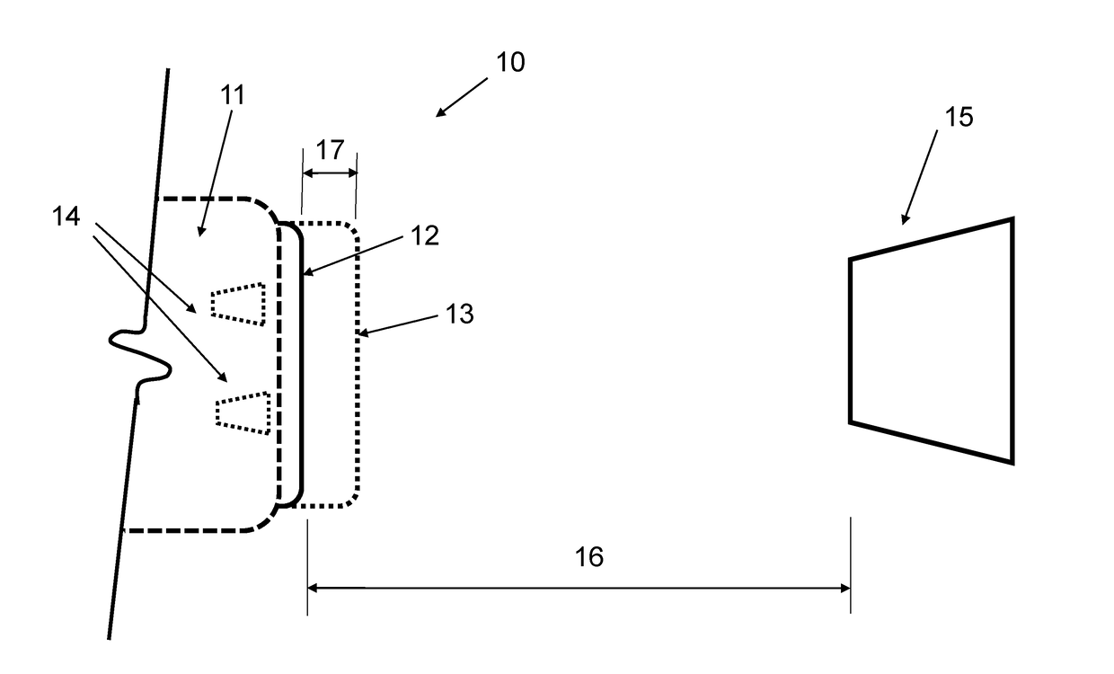
[0014]A schematic of the first embodiment is shown in FIG. 1. In FIG. 1, the frontal (or rear) section 11 of a vehicle is shown which is equipped with the deployable bumper 12, shown in its pre-deployment position with solid lines. The vehicle is considered to be equipped with a sensory system (not shown but consisting of appropriate electronics depending on the type of sensor being used and preferably equipped with one or more microprocessor to perform velocity and acceleration and other related calculations) with at least one sensor 14, which can detect the distance between the (un-deployed) bumper 12 and any stationary or moving object 15 in the path of motion of the bumper. Such sensors are well known in the art, such as sonar sensors which bounce a sound wave off of an object in the sensors path and measures any signal returning to the sensor and the time it takes to receive the return signal. RF based sensors or laser sensors can also be used.

[0015]Then when the sensors 14 of ...

embodiment 20

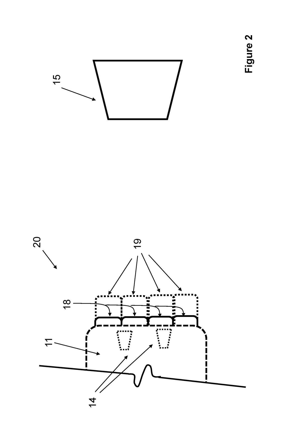
[0022]In the embodiment 20 shown in the schematic of FIG. 2, the deployable bumper 18 is shown to be constructed of several segments (four in FIG. 2) which can be independently deployed. It is, however, appreciated by those skilled in the art that the bumper may be similarly constructed with several rows of segments or in any other proper shapes and arrangements. The frontal view of one such deployable bumper that is constructed with two rows (indicated by numerals 21 and 22) of four segments (indicated by numerals 23 and 24 for the rows 21 and 22, respectively) is shown in FIG. 3. By providing several segmented deployable bumpers, each individual segment in each rows may be independently deployed to achieve maximum effectiveness. At low speeds and if only a small object is being encountered, the bumper deploying control unit will then also have the option of deploying any one or more of the required bumper segments.

[0023]In the embodiments of FIGS. 2 and 3, the deployable bumpers a...


PUM


Abstract

A method for protecting an automobile, the method including: detecting one or more conditions indicative of an impending collision; and deploying one or more bumpers on the automobile for absorbing at least some energy of the collision.

Description

BACKGROUND OF THE INVENTION[0001]1. Field of the Invention[0002]The present invention relates generally to vehicle bumpers, and more particularly to vehicle bumpers that are deployable when collision with an object is detected by the vehicle sensors to significantly increase the range of bumper deformation upon impact, thereby significantly reduce impact induced impulsive forces and energy absorption.[0003]2. Prior Art[0004]Bumpers are used on motor vehicles to absorb low level impact forces and to limit the amount of damage sustained to the vehicle body during high level impacts. To increase the effectiveness of bumper systems in vehicles in terms of reducing impact induced forces and impact energy absorption, the size in the outward direction (outward projection) of the bumper has to be increased to reduce the level of impact induced impulsive forces by spreading the force over longer durations, i.e., to allow for larger deformation of the bumper in the direction of the applied im...

Claims


Application Information

Patent Timeline
IPC IPC(8): B60R19/48B60R19/04B60R19/02
CPCB60R19/483B60R19/04B60R19/023B60R19/18B60R19/205B60R19/40B60R2019/186
Inventor RASTEGAR, JAHANGIR S.
Owner OMNITEK PARTNERS LLC
Why Eureka
Try Eureka