Control of an internal combustion engine in a vehicle

a technology of internal combustion engine and control device, which is applied in the direction of electric control, machines/engines, road transportation, etc., can solve the problems of insufficient reduction and fuel consumption, and achieve the effect of reducing the request of positive engine torque, fuel saving, and reducing fuel injection

Active Publication Date: 2017-07-13
SCANIA CV AB
View PDF20 Cites 9 Cited by
  • Summary
  • Abstract
  • Description
  • Claims
  • Application Information

AI Technical Summary

Benefits of technology

[0010]In the event of e.g. downhill slopes, or in situations where the vehicle must reduce its actual speed, fuel savings have historically been made through a reduced request of positive engine torque, or with the help of dragging. The reduced request of positive engine torque entails that the force driving in the direction of travel, emitted by the combustion engine via the driving wheels, is reduced, e.g. through reduced fuel injection into the engine, which reduces the fuel consumption.

Problems solved by technology

A reduction of the requested engine torque and dragging does indeed reduce fuel consumption, but this reduction is not always optimal, because the reduced engine torque nevertheless often consumes more fuel than necessary, and because the dragging also adds an engine braking, which is not fuel economical, of the vehicle.

Method used


Image

  • Control of an internal combustion engine in a vehicle
  • Control of an internal combustion engine in a vehicle
  • Control of an internal combustion engine in a vehicle

Examples


Embodiment Construction

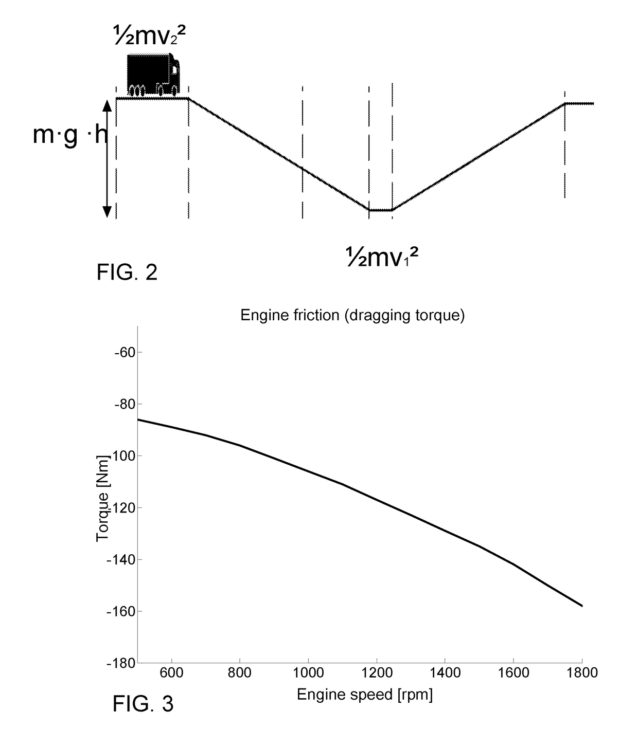
[0041]FIG. 2 shows schematically a non-limiting example of a driving situation, a downhill slope, where the present invention may be applied. The invention may also be applied in other driving situations, for example at a speed reduction, which may occur on a flat road. However, the driving situation in FIG. 2 will here, for pedagogical reasons, be used to describe principles used by the invention.

[0042]For the vehicle in FIG. 2, an energy relationship may be set up for the driving situation:

mgh=(½mv22−½mv12)+(Fair+Frr+Feng+Fgb+Faxle / nav)·s  (equation 1)

where:[0043]mgh is the vehicle's potential energy;[0044]½mv22 is the vehicle's kinetic energy up on the top of the hill;[0045]½mv12 is the vehicle's kinetic energy at the end of the slope;[0046]Fair is the vehicle's air resistance;[0047]Frr is the vehicle's rolling resistance;[0048]Feng is the engine friction;[0049]Fgb is the gearbox friction;[0050]Faxle / nav is friction in the rear shaft, seals and wheel bearings; and[0051]s is the d...


PUM


Abstract

Methods and systems are provided for control of a combustion engine in a vehicle. In operation, at least one future speed profile for an actual speed of the vehicle is simulated during a road section ahead based on information about the road section and on knowledge that coasting with the combustion engine shut down will be applied during the road section. Subsequently, based on the future speed profile, a starting point in time is determined, when the combustion engine will need to be started for forward driving the vehicle and/or to brake the vehicle. Subsequently, a starting point brought forward in time is determined based on the need for a forward driving or braking force arising, where the starting point brought forward in time precedes the starting point in time. Subsequently, the combustion engine is controlled to be started at the starting point brought forward in time.

Description

CROSS-REFERENCE TO RELATED APPLICATION(S)[0001]This application is a national stage application (filed under 35 §U.S.C. 371) of PCT / SE15 / 050701, filed Jun. 16, 2015 of the same title, which, in turn claims priority to Swedish Application No. 1450872-5, filed Jul. 7, 2014 of the same title; the contents of each of which are hereby incorporated by reference.FIELD OF THE INVENTION[0002]The present invention relates to methods, systems, and computer program products for control of a combustion engine during a road section.BACKGROUND OF THE INVENTION[0003]For motor vehicles, such as cars, trucks and buses, the cost of fuel constitutes a significant expense for the vehicle's owner or user. For a hauling company, for example, the main expenditure items for the day-to-day operation of a vehicle consist, apart from the cost of acquisition of the vehicle and the vehicle's driver's salary, of costs of repair and maintenance and fuel for the propulsion of the vehicle. The fuel cost may impact t...

Claims


Application Information

Patent Timeline
Patent Type & Authority Applications(United States)
IPC IPC(8): F02D41/06B60W30/14B60W10/196B60W50/00B60W10/06F02D41/26B60W30/18
CPCF02D41/065B60W2520/10B60W30/143B60W30/18072B60W50/0097B60W10/06B60W10/196F02D2200/602F02D2200/702B60W2420/42B60W2420/52B60W2510/0676B60W2510/184B60W2550/142B60W2550/143B60W2550/406B60W2710/0666B60W2710/184B60W2720/10B60W2710/0688B60W2510/0657F02D41/26B60W10/18B60W30/1843F02D41/06F02D41/12F02D2200/501F02D2200/701F02D2041/1412B60W2556/60B60W2552/20B60W2556/50B60W2556/65B60W2552/15Y02T10/60B60W40/105B60W2720/103B60W2030/1809
Inventor ROOS, FREDRIKOGREN, MIKAELLARSSON, OLOF
Owner SCANIA CV AB
Why Eureka
Try Eureka