
Controller of vehicle and vehicle

a controller and vehicle technology, applied in the direction of automatic clutches, mechanical devices, clutches, etc., can solve the problems of inconvenience, excess torque transmission, distorted power transmission routes, etc., and achieve the effect of suppressing the generation of excess torque in the power transmission route without increasing the mass and cost of the vehicl

Inactive Publication Date: 2017-07-13
TOYOTA JIDOSHA KK
View PDF3 Cites 3 Cited by
  • Summary
  • Abstract
  • Description
  • Claims
  • Application Information

AI Technical Summary

Benefits of technology

The patent describes a controller for a vehicle's automatic clutch that can prevent excess torque without adding extra weight or cost to the vehicle. The controller uses sensors to detect if the vehicle is currently undergoing excess torque and will then adjust the clutch to prevent it. This means that the automatic clutch can maintain its torque capacity even if the driver accidentally engages the clutch in a way that causes excess torque. By doing this, the controller can prevent damage to the vehicle's transmission and other components without increasing the cost or weight of the vehicle.

Problems solved by technology

As a result, the entire power transmission route for driving the drive wheels is distorted, and excess torque is transmitted to the transmission and the like.
Under this circumstance, in the cases where the torque capacity of the automatic clutch is set to have the surplus in consideration of the thermal expansion and the slight thermal expansion occurs, such inconvenience occurs that the excess torque, which is higher than the torque output from the drive source, is generated in the power transmission route due to the surplus set for the torque capacity of the automatic clutch.
In addition, in the cases where a rotational speed of the drive wheel side is higher than the engine speed and the automatic clutch is abruptly engaged during traveling at a high vehicle speed, for example, such inconvenience that the excess torque is generated in the power transmission route also occurs.
However, such a problem arises that mass and cost of the vehicle are increased in this case.

Method used


Image

  • Controller of vehicle and vehicle
  • Controller of vehicle and vehicle
  • Controller of vehicle and vehicle

Examples


Embodiment Construction

[0025]A detailed description will hereinafter be made on an embodiment of the disclosure with reference to the drawings. Note that, in the following embodiment, the drawings are appropriately simplified or deformed, and thus dimensional ratios, a shape, and the like of each component are not necessarily shown accurately.

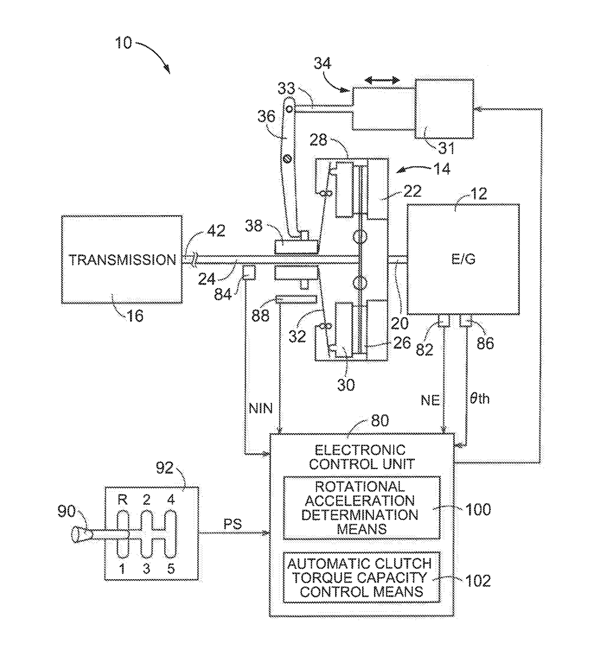
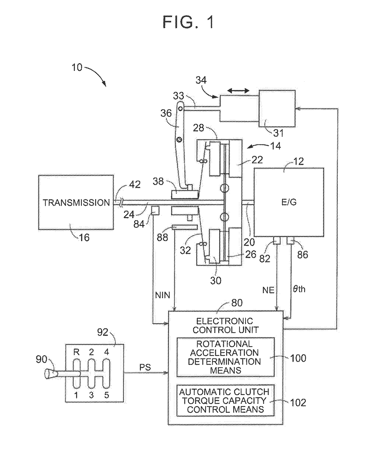
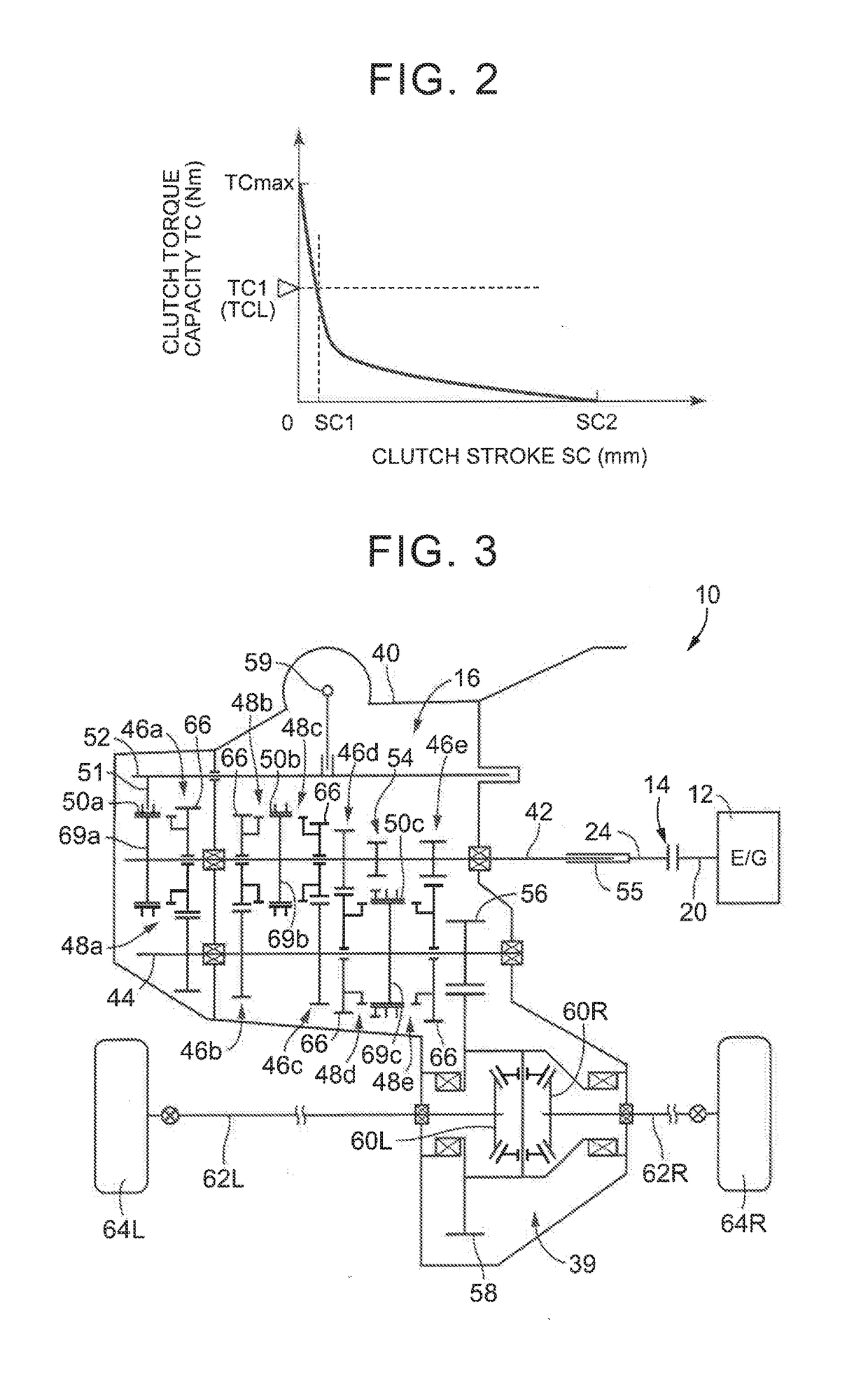
[0026]FIG. 1 is a skeletal view for illustrating a schematic configuration of a vehicle drive unit 10, to which the disclosure is applied, and is a view for schematically illustrating a control configuration for controlling an automatic clutch 14 as a part of the vehicle drive unit 10. As shown in FIG. 1, the vehicle drive unit 10 is used for an FF vehicle, for example, and includes an engine 12 as a travel drive source, the automatic clutch 14, a transmission (automatic transmission) 16, and the like.

[0027]The transmission 16 is formed of a constant-mesh transmission with parallel shafts, for example. The transmission 16 is configured that a specified gear stage is ...


PUM


Abstract

A controller including an electronic control unit, the electronic control unit is configured to determine at least one of whether a first absolute value is at least equal to a first threshold and whether a second absolute value is at least equal to a second threshold. When the electronic control unit determines that at least one of the first absolute value and the second absolute value is at least equal to the corresponding threshold, torque capacity of an automatic clutch is controlled such that the automatic clutch is brought into a slipping state. The first absolute value is an absolute value of rotational acceleration of an input shaft of a transmission, and the second absolute value is an absolute value of rotational acceleration of drive wheels.

Description

INCORPORATION BY REFERENCE[0001]The disclosure of Japanese Patent Application No. 2016-004813 filed on Jan. 13, 2016 including the specification, drawings and abstract is incorporated herein by reference in its entirety.BACKGROUND[0002]1. Technical Field[0003]The disclosure relates to a controller for a vehicle and a vehicle and, in particular, to improved responsiveness of the automatic clutch.[0004]2. Description of Related Art[0005]A vehicle that includes an automatic clutch in a power transmission route from a drive source, such as an engine, to drive wheels has been known, and the automatic clutch controls clutch strokes by using an actuator, so as to control torque transmitted between the engine and a transmission. For instance, an automatic clutch described in Japanese Patent Application Publication No. 02-163520 (JP 02-163520 A) is a typical example. In this automatic clutch of JP 02-163520 A, a relationship between engaged torque capacity of the automatic clutch and each of...

Claims


Application Information

Patent Timeline
Patent Type & Authority Applications(United States)
IPC IPC(8): F16D48/06
CPCF16D48/06F16D2500/10412F16D2500/1107F16D2500/507F16D2500/70426F16D2500/50287F16D43/21F16D43/24F16D2500/1085F16D2500/30818F16D2500/3114F16D2500/3115
Inventor MIYAZONO, HIDEAKI
Owner TOYOTA JIDOSHA KK
Learn More