
Comminution device and method for operating such a comminution device

Inactive Publication Date: 2017-07-20
INTIMUS INT
View PDF6 Cites 1 Cited by
  • Summary
  • Abstract
  • Description
  • Claims
  • Application Information

AI Technical Summary

Benefits of technology

The invention provides a comminution device that is suitable for stable, smooth, and potentially thick products. The design of the cutting discs and teeth, as well as their arrangement on the cutting discs and rollers, has been found to be advantageous for this type of product. The teeth on the cutting discs are symmetrically arranged in relation to a central plane between the cutting rollers, which ensures stable and smooth operation. The spacing of the teeth on the cutting discs is uniform, simplifying manufacturing. The piloting device is designed to guide the product for comminution smoothly up to the comminution unit without causing any lateral movement.

Problems solved by technology

However, these comminution devices are not suitable for mobile terminal apparatuses such as mobile phones or tablet computers, for example.

Method used


Image

  • Comminution device and method for operating such a comminution device
  • Comminution device and method for operating such a comminution device
  • Comminution device and method for operating such a comminution device

Examples


Embodiment Construction

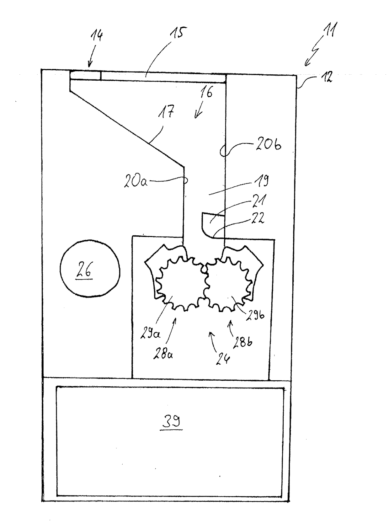
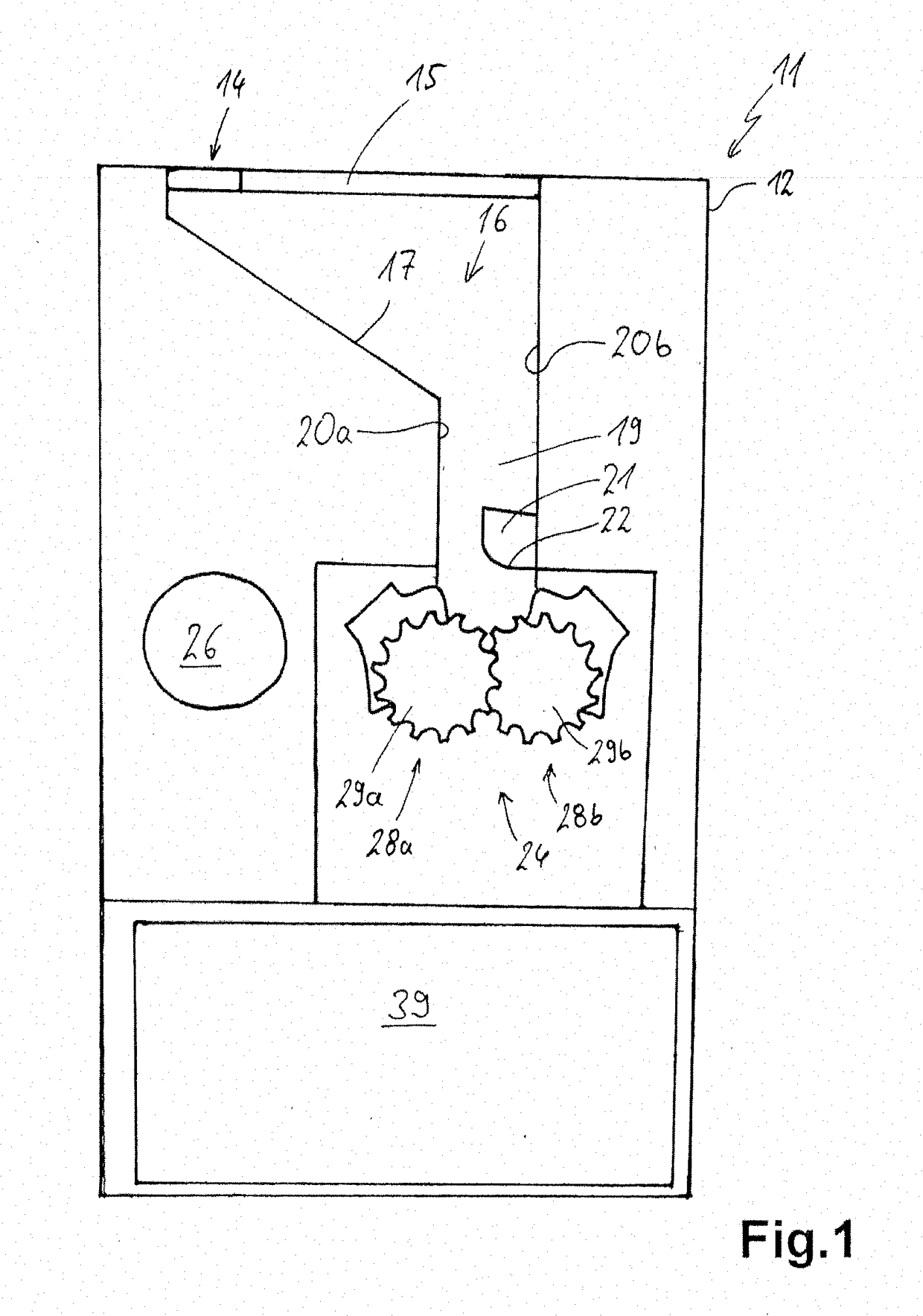
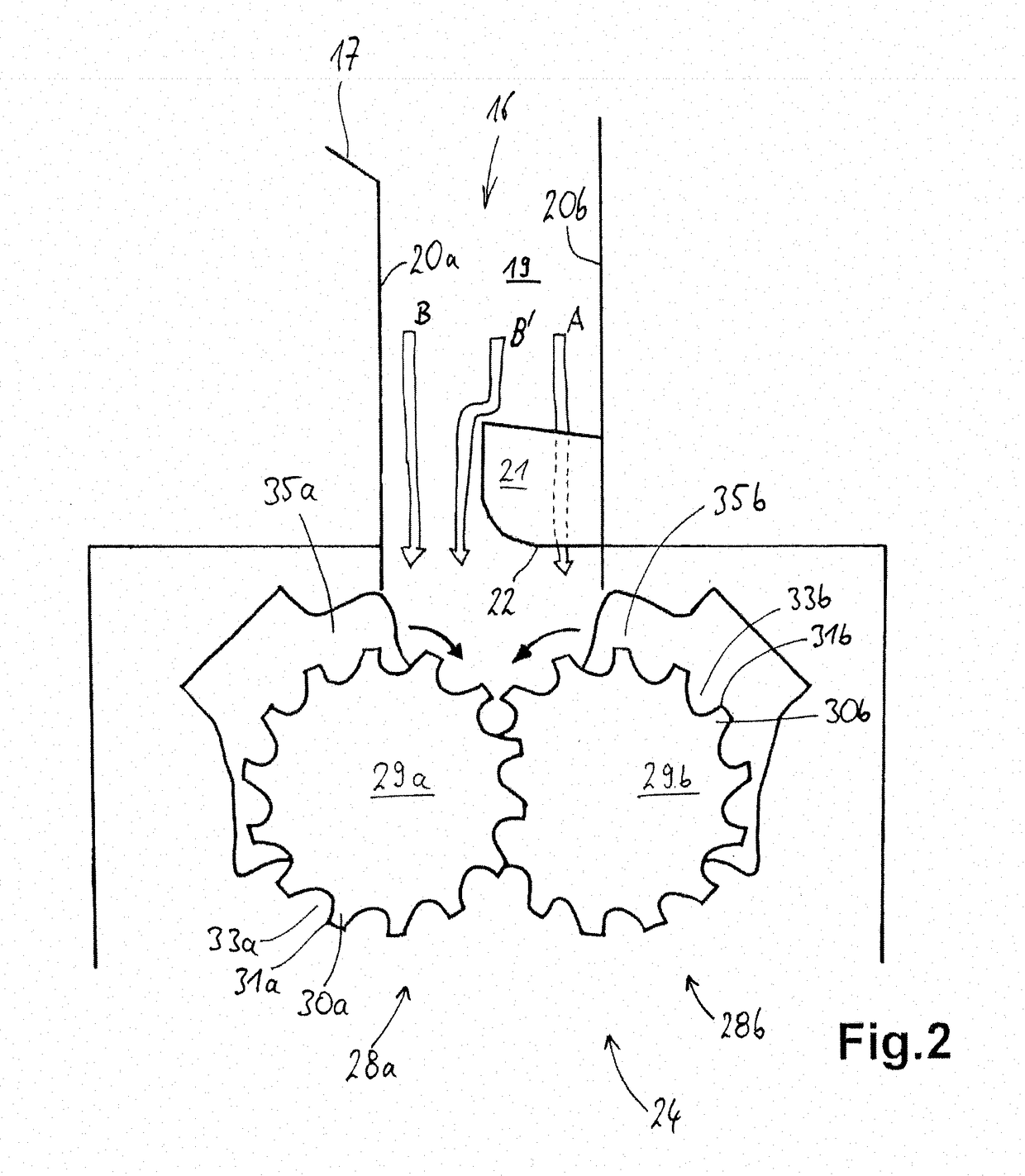
[0031]A comminution device 11 according to the invention, such as may be used in an office or a smaller enterprise, for example, for comminuting the product for comminution mentioned at the outset, or above all for destroying the digital data stored therein, respectively, is illustrated in FIG. 1. The comminution device may be approx. 0.8 m to 1.5 m in size and advantageously be operated by a usual mains connection.

[0032]The comminution device 11 has a housing 12 having a slot-type infeed opening 14 having the exemplary dimensions of 4 cm×16 cm and being long and wide enough for the product for comminution envisaged. An infeed 16 having an oblique infeed track 17 adjoins the infeed opening 14 on the upper side of the comminution device 11. Said infeed track 17 leads to a guide duct 19, or transitions directly into one of the walls 20a and 20b of the latter, respectively, specifically into the left wall 20a. The guide duct 19 herein runs vertically, but this is not mandatory. Said gu...


PUM


Abstract

A comminution device for product for comminution such as memory cards or mobile terminal apparatuses has a comminution unit which has two interacting cutting rollers having cutting discs that have cutting edges on the external peripheral edges and form a cutting gap. The cutting discs of the one cutting roller each engage in an annular groove between adjacent cutting discs of the other cutting roller and along the external circumference have a plurality of teeth, each having one tooth tip and one tooth blade. The tooth blades of the one cutting roller during operation upon rotation of the cutting rollers each lie beside the tooth blades of the other cutting roller. The comminution unit yet has an infeed having an infeed track for the product for comminution to the comminution unit, said infeed track terminating above the cutting gap. An elongate piloting device which extends across a length of at least 30% of the length of the cutting rollers, and which in the longitudinal profile thereof slopes downward is disposed therebetween.

Description

CROSS-REFERENCE TO RELATED APPLICATION[0001]The present application claims priority to German Patent Application No. 10 2016 200 756.4, filed Jan. 20, 2016, the entirety of which is incorporated herein by reference.FIELD OF APPLICATION AND PRIOR ART[0002]The invention relates to a comminution device for product for comminution such as memory cards, mobile terminal apparatuses or the like, that is to say in particular relatively stable, flexurally rigid, and in part thick or voluminous, respectively, and potentially smooth product for comminution. The invention furthermore relates to a method for operating such a comminution device.[0003]Various similar comminution devices, also referred to as shredders, are known from the prior art. Said comminution devices may not only be configured for comminuting paper but also for CDs, such as in the case of DE 19912036 A1, for example, or for various other media, such as in the case of DE 10008442 A1, for example. However, these comminution dev...

Claims


Application Information

Patent Timeline
IPC IPC(8): B02C18/18B02C18/22B02C25/00
CPCB02C18/182B02C18/2291B02C25/00B02C18/142B02C2018/0015B02C2018/0023
Inventor DE ZARATE, JAVIER ORTIZ
Owner INTIMUS INT
Learn More