Fluid transfer of suction force between drawback apparatuses

a drawback apparatus and suction force technology, applied in the direction of cooled electrodes, engine diaphragms, diaphragm valves, etc., can solve the problems of substantial liquid spillage, hazardous to operations personnel, and/or potentially dangerous spillage, so as to reduce or eliminate liquid loss

Active Publication Date: 2017-07-20
PROTEUS INDUSTRIES INC
View PDF0 Cites 3 Cited by
  • Summary
  • Abstract
  • Description
  • Claims
  • Application Information

AI Technical Summary

Benefits of technology

[0007]Some embodiments described herein reduce or eliminate liquid loss (e.g., spillage) in liquid cooling systems which may operate in high electrical current environments. Various embodiments described herein discuss drawback of liquid coolant from fluid paths of the liquid cooling system For example, in some embodiments, the system may drawback liquid coolant from the fluid paths in preparation for a scheduled system maintenance or repair, and / or it may draw back liquid coolant in response to a failure of one or more system components (e.g., welding electrodes).
[0014]An exemplary method may be provided for cooling welding electrodes. The method may include cooling a first welding electrode by circulating liquid coolant through a first electrode path in fluid coupling with the first welding electrode. The flow of liquid coolant through the first liquid path may be reduced or stopped when the first electrode at least partially detaches, and the liquid coolant may be drawn back from a gap in the first electrode path that is formed when the first welding electrode at least partially detaches.
[0015]Some embodiments describe cooling a second welding electrode by circulating liquid coolant through a second electrode path in fluid coupling with the second welding electrode, stopping or reducing flow of the liquid coolant through the second liquid path when the second electrode at least partially detaches, and drawing back the liquid coolant from a gap in the second electrode path that is formed when the second welding electrode at least partially detaches.

Problems solved by technology

However, the welding electrodes are designed to be removed from the welding machine (e.g., during a failure or for a scheduled maintenance) which can cause substantial liquid spillage.
Such spillage may be harmful to the welding equipment, hazardous to operations personnel, and / or potentially dangerous in an environment of high electrical current.
Although current systems may reduce spillage to some degree by simply shutting off liquid flow at the source when a welding electrode is lost or removed, this is not optimal because spillage can still occur from liquid already circulating in the cooling system.

Method used


Image

  • Fluid transfer of suction force between drawback apparatuses
  • Fluid transfer of suction force between drawback apparatuses
  • Fluid transfer of suction force between drawback apparatuses

Examples


Embodiment Construction

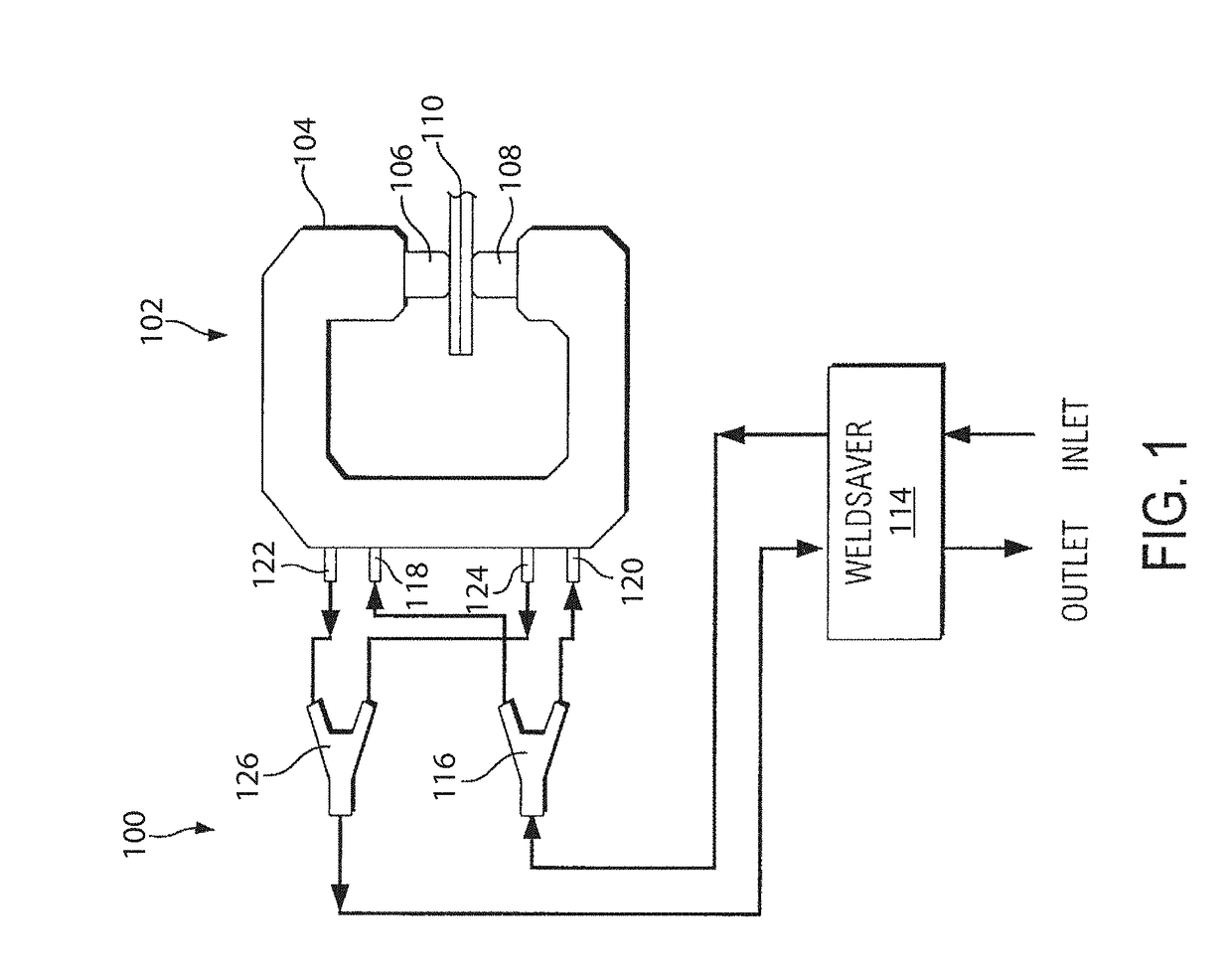
[0050]FIG. 1 is a diagram of a fluid flow system 100 for cooling one or more components of a welding machine according to some embodiments. The system 100 is illustrated as being a resistance welding system, although embodiments described herein are not limited to any particular system or application. At least some of the embodiments described herein may be advantageously utilized in any fluid flow system in which it is desired to liquid cool component(s) and / or drawback fluid from one or more flow paths (or “passageways”).

[0051]The system 100 includes a resistance welding machine 102 having a hollow frame 104 which supports two vertically opposed welding electrodes 106 and 108 made of copper or other suitable material. The electrodes 106 and 108 may also be known as welding tips or caps. In operation, a work piece 110, typically consisting of two or more metal sheets, can be clamped between the electrodes 106 and 108 and an electrical voltage can be applied across the electrodes 10...


PUM

PropertyMeasurementUnit
volume capacityaaaaaaaaaa
motive suction forceaaaaaaaaaa
suction forceaaaaaaaaaa

Abstract

A first electrode coolant path is configured to cool a first welding electrode by liquid coolant flowing from a supply path through the first electrode coolant path to a return path. A second electrode coolant path is configured to cool a second welding electrode by liquid coolant flowing from the supply path through the second electrode coolant path to the return path. Three or more valves are configured to stop or reduce liquid coolant flow through the first or second electrode coolant path and configured to stop or reduce liquid coolant backflow from the return path when the first or second welding electrode is at least partially detached. At least one valve is coupled in the first or second electrode coolant path. A drawback apparatus generates a suction force to draw liquid coolant away from a gap formed when the first or second welding electrode is at least partially detached.

Description

CROSS-REFERENCE TO RELATED APPLICATIONS[0001]The present application is a continuation of U.S. patent application Ser. No. 14 / 849,247, filed Sep. 9, 2015 and entitled “Systems and Methods for Coolant Drawback,” and is a continuation of U.S. patent application Ser. No. 14 / 849,307, filed Sep. 9, 2015 and entitled “Drawback Valve Systems and Methods for Coolant Drawback,” both of which claim priority to U.S. Provisional Patent Application Ser. No. 62 / 048,168, filed Sep. 9, 2014 and entitled “Water Drawback,” all of which are hereby incorporated by reference herein.BACKGROUND[0002]1. Technical Field[0003]The present invention(s) relate generally to liquid cooling systems. More particularly, the invention(s) relate to systems and methods for cooling welding electrodes and reducing coolant loss.[0004]2. Description of Related Art[0005]Resistance welding (e.g., spot welding) machines require cooling systems to operate effectively. Typically, water cooling systems are used to cool the machi...

Claims


Application Information

Patent Timeline
Patent Type & Authority Applications(United States)
IPC IPC(8): B23K11/30
CPCB23K11/3072B23K11/3018B23K11/115F16K23/00F16K37/005B23K11/3054F04B53/14F04B43/02F16K7/12F16K31/16F17D3/01F04B43/14H05K7/20H05K7/20218H05K7/20272F15B3/00
Inventor NICEWONGER, MARK
Owner PROTEUS INDUSTRIES INC
Why Eureka
Try Eureka