Hydraulic prosthetic joint

a prosthetic joint and hydrophilic technology, applied in the field of artificial legs, can solve the problems of unwelcome stares of amputees, knees becoming automatically locked, and resistance often so grea

Active Publication Date: 2018-10-02
BOENDER JACOB QUINTUS LAURENCE ANTHONY +1
View PDF7 Cites 1 Cited by
  • Summary
  • Abstract
  • Description
  • Claims
  • Application Information

AI Technical Summary

Benefits of technology

[0020]In accordance with the present invention, there is provided a prosthesis in accordance with the features of claim 1. The prosthesis, under normal conditions has a hydraulic damper wherein a fluid flow rate of the incompressible hydraulic fluid through the valve is a conditioned function of a second pressure, which second pressure is less than the first pressure and is associated with fluid flow through the valve and is operable to maintain a positive flow rate through the valve as the first pressure increases, the conditioned function being determined such that the second pressure as a function of the flow rate causes an increase in resistance of the valve to the flow caused by the first pressure, such that the fluid flow approaches but does not reach a maximum as the first pressure increases past a minimum pressure, whereby a fluid flow limit is established through the valve. A sensor to flow and or pressure is therefore also provided, which sensor conveniently enables control of an additional control element, for example under the control of a magnetic field, to enable control of a moveable body which acts upon the valve to enable an increase or decrease of flow of hydraulic fluid through the valve. Piezoelectric, magnetic, electromagnetic, and / or electrical signals can otherwise or additionally be employed in the provision of this sensor. Control of flow about or through a valve flow control element can conveniently be determined by one of a microprocessor, analogue or electrical switched circuits. That is to say, the sensor can cause an additional control element to operate whereby, where the limb is a leg, to enable an increase in gait by way of reduction of resistance to flow or to reduce or stop flow by way of a stumble recovery mechanism. The device can comprise a rotary or oscillatory sensor, whereby to create an electrical pulse or wave that carries information about the state of flow and change in rate of flow. This electrical signal can then be separated in information and now redundant energy. This energy can then be re-modulated via a microprocessor into a signal to drive an electro-fluidic valve or electro-fluidic transistor. A small current passing through the coil of the valve device alters the tension on the movable valve body as to act as the regulator of the flow rate, independent of main driving pressure as known from the prior art. In the limit, upon a reversal of current through a valve coil can cause closure of a valve, a function neither disclosed nor suggested in the prior art. The present invention can therefore provide a controllable variable force that can more rapidly alter the properties of the valve.
[0021]By the provision of a hybrid construction in having both a mechanical resilient member as well as a piezoelectric, electromagnetic, electrostatic or magnetic force acting on the same moveable skirt of the valve can have advantages: the resilient member can take responsibility for the normal function of the valve, having a passively determined dynamic response of the knee joint as disclosed in, for example, U.S. Pat. No. 8,915,969, and therefore not requiring electrical power for total movement control, which electrical power needs to be provided by some power source, such as a battery of electrical storage cells, but with the added advantage of fine tuning control of the magnetic force or other known means of creating forces by electrical means such as electrostatics and piezoelectrics. The present invention can thus utilize an electrical measure of a rate of change of flexion as a source of system control upon a hydraulic valve, whereby to enable a variation in a pressure differential across a valve and thus to improve, in the case of a prosthetic leg, stumble recovery on the one hand and on the other hand to enable a variation in damping control to enable stability of use, irrespective of rate of a user's gait.
[0023]In the event that the flow stops instantaneously, then a stumble recovery mode could be instigated, causing fluid flow through a valve to be minimized or even prevented: instead of maintaining the valve in a controlled open state by preventing valve closure by magnetic force, a field reversal would instead force rapid valve closure. The vane could be connected to a microprocessor to determine when valve operation needs to be varied from a quiescent state. In the alternative a dc voltage could be generated which could be either employed directly to control a valve control mechanism or be amplified. The electricity output from a small generator is conveniently damped and stored using capacitors. An electromagnet or other positioning unit can be employed to alter the operating characteristics of a valve; from being fully closed in a stumble recovery mode to a condition of providing less resistance when an increase in gait is desired, the valve acting between two chambers of a damper can be further, additionally controlled.

Problems solved by technology

It can be said that the test is somewhat subjective if one were to view an amputee with an artificial leg, but mere observation is one of the best tests; a strange gait is generally immediately apparent; this can cause unwelcome stares to amputees, who when fitted with a pair of long trousers would otherwise not be noticed when in a crowd.
In this device, however, an axial load on the limb produced a small rotation of the radius arm or arms causing the brake band or brake shoe to grip the drum and to resist knee flexion.
Indeed, the resistance would frequently become so great such that the knee became automatically locked once sufficient load had been applied.
In some situations, however, this system required an amputee to make a knee-extending movement before flexion could be initiated.
Additional problems arose through external wear and through the fact that they require actuation, which is, of course dependent upon movement being regular.
In some cases mechanical switching of the valve will not be effected properly.
While recent hydraulic devices are believed to be much improved they are complex and costly to manufacture since they are manufactured to high tolerances.
On the one hand, if mechanical external valve control is provided, then there will be problems as discussed above; on the other hand, electronic flow control valves can be provided—that are expensive to purchase and maintain—which enable amputees to walk with a pre-determined gait yet will not necessarily be reactive to uneven surfaces.
In simple terms, to the casual observer, the person wearing such artificial limbs would be seen to have an ungainly gait due to a delay in knee extension needed to prepare the limb for weight acceptance.
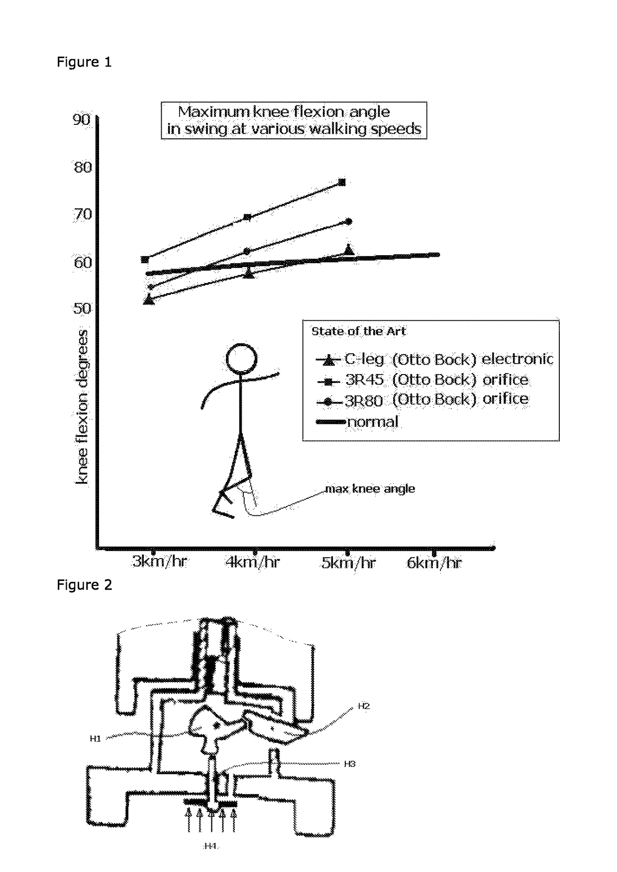
A horizontal response was produced but the study was limited to below 5 km / hr limit, which is less than normal walking speeds.
Problems arising from the use of weight activated knee joint control mechanisms include the fact that the residual weight taken by the artificial limb on toe-off can inhibit a release of the weight-activated mechanism.
Whilst this threshold is easily overcome by forces passing through the heel, the threshold is not easily overcome by forces passing through the toe.
Nevertheless, this threshold reduces the chance of unintentional activation on heel strike, but means that some attention needs to be paid as to how one walks with such a prosthesis at all times. This threshold also makes it difficult to maintain stability of the knee, when extension after mid swing is incomplete the respective foot is susceptible of hitting the ground too early.
Typically the weight-activation class of knee joints do not provide security against collapse in such conditions or in the event of accidental use.
One difficulty to be overcome by users of prosthetic lower limbs is that it is counter intuitive to place one's body weight onto the device to secure the same body weight against sudden collapse.
In the event of an inadvertent early reapplication of weight on the prosthesis, the toggle would likely not be in a position to allow closure of the valve, which could be painful and perhaps cause an amputee to fall over following knee collapse in such circumstances.
This is referred to as a stumble recovery problem.
In addition to the abovementioned stumble problem, another issue of note is that when a prosthetic lower limb is correctly fitted, it will tend to be fitted to provide appropriate levels of resistance to movement whilst the amputee is walking at what is a comfortable pace.
Any increase in speed results in a burden arising from the damper settings providing too much resistance if the amputee wishes to go faster or, indeed, does not provide sufficient resistance at a speed at a normal rate.
A perceived shortcoming in this approach is that the metering aperture is not easily controlled in an on-demand fashion, with the functionality of the valve is necessarily determined as a function of fluid flow and positions of associated elements of the damper arrangement.

Method used


Image

  • Hydraulic prosthetic joint
  • Hydraulic prosthetic joint
  • Hydraulic prosthetic joint

Examples


Embodiment Construction

Definitions

[0037]The following terms have specific meanings and it is intended that reference shall be made to this lexicon in event of any doubt:

[0038]Brace: a support device to maintain a relative position of a limb with respect to the trunk or another limb; part of an external framework arranged about and intended to support limbs.

[0039]Hydraulic fluid: a substantially incompressible fluid operable in hydraulic lines, hydraulic rams and hydraulic systems.

[0040]Hydraulic damper: a hydraulic device comprising at least a first variable volume of hydraulic fluid, wherein the volume of hydraulic fluid retained within the hydraulic actuator is proportional to an amount of actuation associated with a joint to which the hydraulic damper is coupled.

[0041]Prosthesis: an artificial part such as an artificial limb; an artificial or mechanical aid such as a brace.

[0042]Prosthetic joint: an artificial joint associated with the repair or replacement of a skeletal joint; the term includes extern...


PUM


Abstract

The present invention relates to artificial limbs generally and to joints for the same. In particular, the present invention provides hydraulic functional units, generally classified as damping devices as connected between artificial limbs whereby enabling movement of artificial joints to closely correspond with natural human movement. In accordance with the invention, there is provided hydraulic damper control elements for prostheses which utilize a pressure differential due fluid flow as a direct control input for a at least one hydraulic valve. The valve can comprise a moveable element which abuts a mounted element which reduces the size of an aperture as the force increases. Further, a moveable body acts upon the valve enabling increase or decrease of flow of hydraulic fluid through the valve, whereby enabling an increase in gait by way of reduction of resistance to flow or reducing or stopping flow by way of a stumble recovery mechanism.

Description

CROSS-REFERENCE TO RELATED APPLICATIONS[0001]This application is a continuation of UK patent application serial number GB 1502504.2, titled, “A HYDRAULIC PROSTHETIC JOINT”, which was filed on Feb. 13, 2015, the entire specification of which is incorporated herewith by reference in its entirety.BACKGROUND OF THE INVENTION[0002]Field of the Art[0003]The present invention relates to artificial limbs generally and to joints for the same. In particular, the present invention provides hydraulic functional units, generally classified as damping devices as connected between artificial limbs whereby to enable movement of artificial joints to closely correspond with natural human movement.[0004]Discussion of the State of the Art[0005]In the provision of realistic joints, as used in prosthetic limbs, an important aspect in attempting to achieve a realistic movement is to provide a different operating characteristic to the joint when under load. Indeed, one of the more important characteristics...

Claims


Application Information

Patent Timeline
Patent Type & Authority Patents(United States)
IPC IPC(8): A61F2/74A61F2/64A61F2/60A61F2/68F16F9/512A61F2/76A61F2/50A61F2/70
CPCA61F2/604A61F2/64A61F2/68F16F9/5126A61F2002/5004A61F2002/5006A61F2002/7655A61F2002/5035A61F2002/6863A61F2002/704A61F2002/74A61F2002/745A61F2002/748A61F2002/5033A61F2/70A61F2/74A61F2/748A61F2/6607A61F2002/5003F16F9/466
Inventor BOENDER, JACOB QUINTUS LAURENCE ANTHONYBOENDER, JONA AELRID BRENDAN
Owner BOENDER JACOB QUINTUS LAURENCE ANTHONY
Why Eureka
Try Eureka