Air intake heater system for a combustion engine, method for heating intake air and a vehicle comprising such a system

a technology for heating intake air and combustion engines, which is applied in the direction of air intake for fuel, combustion air/fuel air treatment, machines/engines, etc., can solve the problems of humidity in the intake system, inability to clean hp egr gas, and high levels of pollutant, so as to minimize the risk of water condensation in lp egr gas

Active Publication Date: 2020-12-15
VOLVO CAR CORP
View PDF9 Cites 0 Cited by
  • Summary
  • Abstract
  • Description
  • Claims
  • Application Information

AI Technical Summary

Benefits of technology

[0009]By this first embodiment of a system for heating intake air of a vehicle, the intake air is heated by a heat exchanger in which HP EGR gas is used as a heat source. At the same time, the HP EGR gas is cooled by the intake air. One advantage of this is that LP EGR gas can be used for recirculation to the air intake of the vehicle at a lower temperature, since the heating of the intake air will reduce condensation of water of the LP EGR gas. A further advantage is that the HP EGR gas is cooled by the intake air, which allows more HP EGR gas to be used to heat the engine at start of the vehicle. If the HP EGR gas is not cooled, it may exceed the allowed temperature at the intake manifold of the combustion engine. By using inlet air to cool the HP EGR gas, it is possible to replace a specific HP EGR gas cooler with the heat exchanger.
[0016]In a further step, the flow of high pressure EGR gas to the intake manifold is reduced or stopped completely when the intake air has reached a predefined temperature. The temperature of the intake air is preferably measured before the turbine inlet. Intake air is here either only the inlet air or the mixture of inlet air and LP EGR gas. The use of LP EGR gas for the recirculation is advantageous in that the LP EGR gas is cleaner and cooler than the HP EGR gas. According to one example embodiment, the flow of high pressure EGR gas to the intake manifold is reduced or stopped completely when the intake air mixture has reached a predefined temperature, and the intake system has been preheated so that the enabled low-pressure exhaust gas recirculating gas mixture will not create condensation when re-circulated into the intake air system.

Problems solved by technology

One disadvantage is that the HP EGR gas is not cleaned in an aftertreatment system and thus contains higher levels of pollutes.
A disadvantage of using LP EGR is humidity at lower ambient temperatures, which causes the humidity to condensate in the intake system of the vehicle, upstream of the turbocharger.
The condensation of water, e.g. inside the air intake, is problematic as during this heat-up phase with LP EGR gas, water from the exhaust gases condensates and an un-controlled amount of water is present in the intake system, in intake coolers, and creates droplets that hit compressor blades of the turbocharger.
The droplets may damage the compressor blades, and the water may freeze.
If the HP EGR gas is not cooled, it may exceed the allowed temperature at the intake manifold of the combustion engine.

Method used


Image

  • Air intake heater system for a combustion engine, method for heating intake air and a vehicle comprising such a system
  • Air intake heater system for a combustion engine, method for heating intake air and a vehicle comprising such a system
  • Air intake heater system for a combustion engine, method for heating intake air and a vehicle comprising such a system

Examples


Embodiment Construction

[0022]The embodiments of the invention with further developments described in the following are to be regarded only as examples and are in no way to limit the scope of the protection provided by the patent claims.

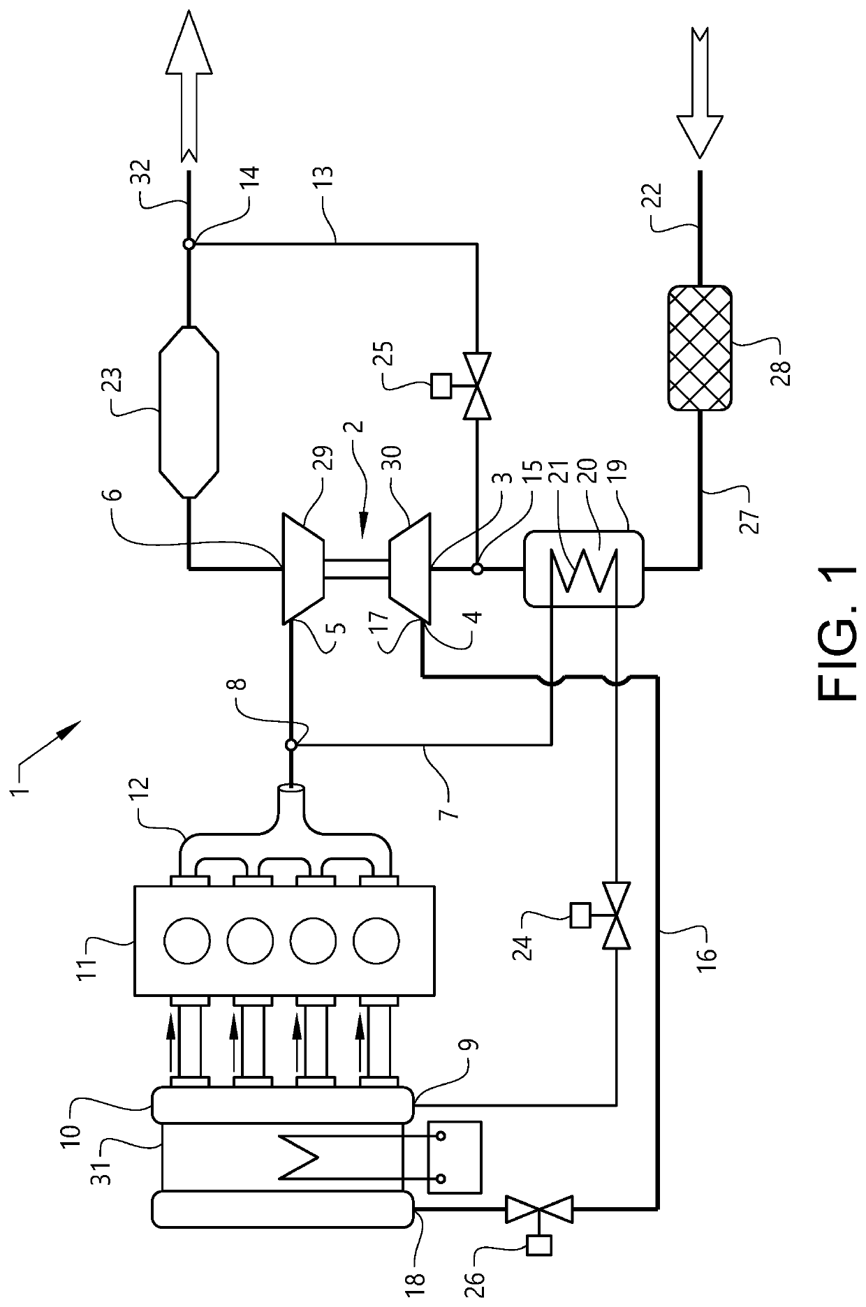
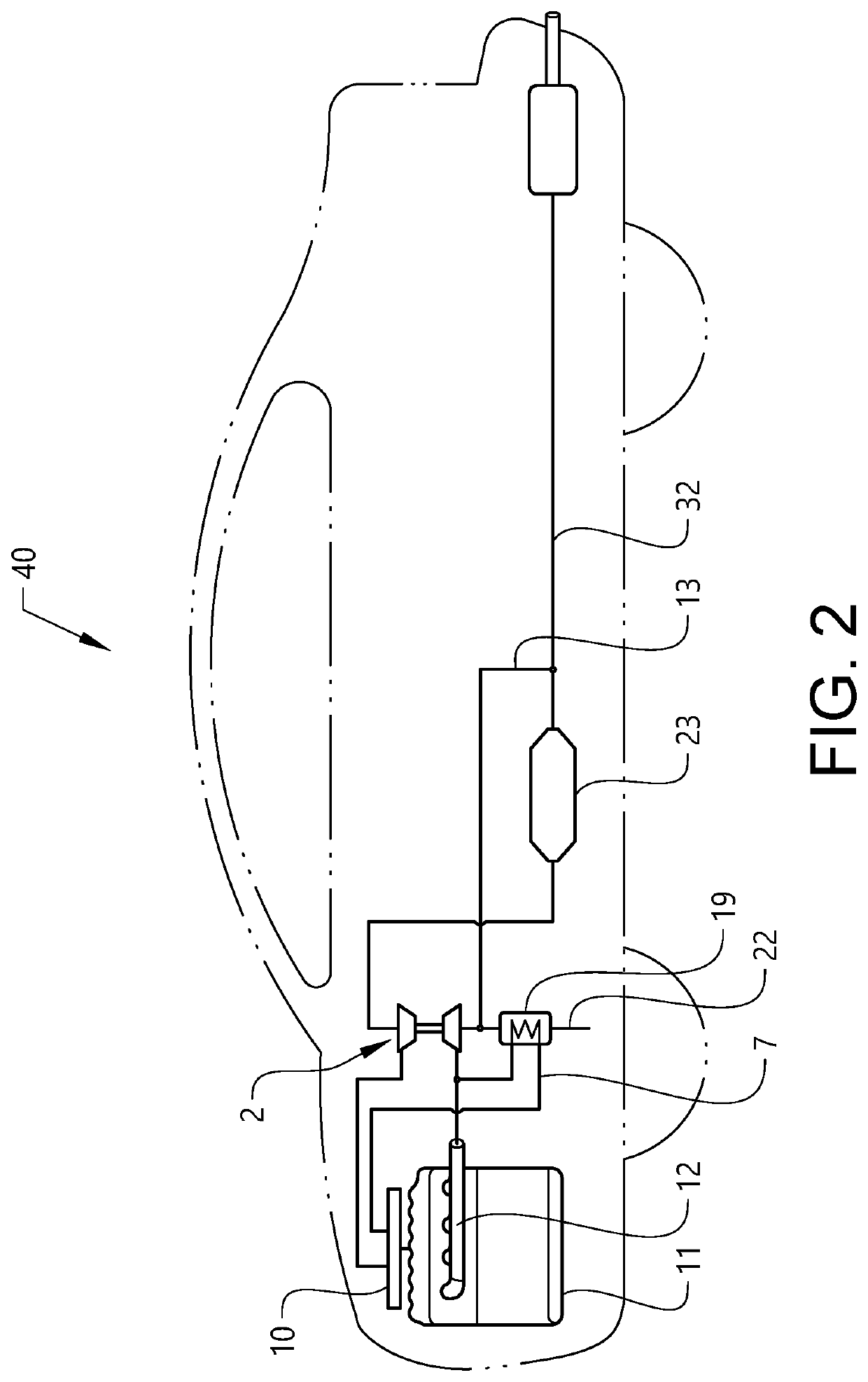
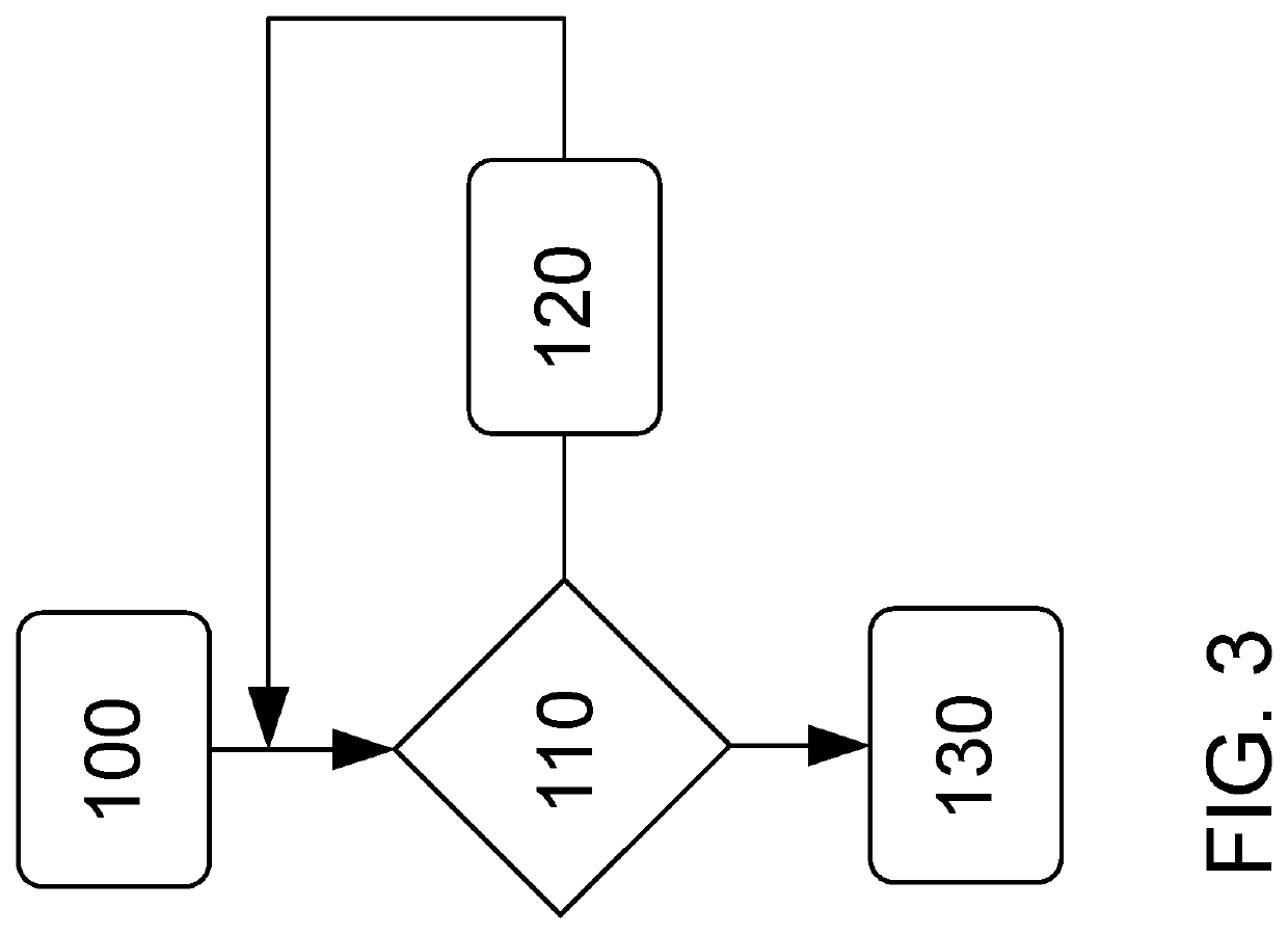
[0023]FIG. 1 shows a first embodiment of a system for heating intake air of a combustion engine, FIG. 2 shows a vehicle comprising such system for heating intake air of a combustion engine, and FIG. 3 shows a schematic flow chart of an inventive method for heating intake air of a combustion engine.

[0024]The air intake heater system 1 is arranged at a combustion engine in a vehicle. The combustion engine may be either a diesel engine or a combustion engine running on petrol, natural gas or the like. The combustion engine may be a spark ignited combustion engine or a sparkplug controlled compression engine. The combustion engine 11 is provided with an air intake manifold 10 adapted to receive and distribute intake air to the inlet of the combustion engine. The combustion engi...


PUM


Abstract

An air intake heater system for a combustion engine, comprising; a turbocharger, a high pressure EGR conduit, a low pressure EGR conduit, and an air intake conduit, where the system comprises a heat exchanger arranged upstream of the turbocharger, where the heat exchanger comprises a first flow channel connecting an air inlet to an inlet of the turbocharger and a second flow channel, where the second flow channel is part of the high pressure EGR conduit. The advantage of the invention is that intake air and low pressure EGR gas can be heated by the high pressure EGR gas, and that high pressure EGR gas can be cooled by intake air.

Description

CROSS-REFERENCE TO RELATED APPLICATION[0001]The present patent application / patent claims the benefit of priority of co-pending European Patent Application No. 18168741.9, filed on Apr. 23, 2018, and entitled “AIR INTAKE HEATER SYSTEM FOR A COMBUSTION ENGINE, METHOD FOR HEATING INTAKE AIR AND A VEHICLE COMPRISING SUCH A SYSTEM,” the contents of which are incorporated in full by reference herein for all purposes.TECHNICAL FIELD[0002]The present invention relates to a system for heating intake air of a vehicle, a method for heating intake air of a vehicle and a vehicle comprising such an intake air heating system.BACKGROUND ART[0003]Vehicles comprising an internal combustion engine are subjected to a plurality of different legislative requirements and regulations. Some of these requirements and regulations are directed to fuel consumption and exhaust emission. Different countries or markets may have different requirements, but most include a specific test cycle that is supposed to give...

Claims


Application Information

Patent Timeline
Patent Type & Authority Patents(United States)
IPC IPC(8): F02M26/42F02M26/09F02M26/35F02M35/10F02M26/05F02M26/06
CPCF02M26/06F02M26/35F02M26/05F02M35/10268F02M26/09F02M26/42F02M31/08F02M26/17F02M26/27F02B29/04F02B37/00F02M31/042F02M31/13F02M26/30Y02T10/12
Inventor ROHRSSEN, KARSTENSVENSSON, PETERSEBESTYEN, RICHARDPERSSON, HÅKAN
Owner VOLVO CAR CORP
Why Eureka
Try Eureka