Wearable mining lamp with uniform auxiliary lights

a mining lamp and auxiliary light technology, applied in the field of illumination technology or mining lamps, can solve the problems of unsatisfactory overall illumination effect during operation, unsatisfactory lighting effect, and negatively affecting work efficiency, and achieve the effect of eliminating significant fluctuations in illumination in the lighting area, uniform brightness, and high quality illumination environmen

Inactive Publication Date: 2017-07-20
WUHAN KINYUN SCI & TECH
View PDF2 Cites 5 Cited by
  • Summary
  • Abstract
  • Description
  • Claims
  • Application Information

AI Technical Summary

Benefits of technology

[0024]The present invention discloses a miniature lamp cup structure of a safe mining lamp, which can regulate the low-beam in a predefined area to provide uniform illumination without light spots, so as to provide a high-quality illumination environment for low-beam operation.
[0025]The present invention reveals a conclusion that has been improved and proved by the applicant by making a large quantity of experiments. In a light source without any convex lens, it is possible to precisely control the size, direction and brightness of the lighting area only by adjusting the angle of the reflecting surfaces, which are a plurality of flat reflecting surfaces having no curvature, and it is possible to eliminate significant fluctuations of illuminance in the lighting area, so as to present a light curtain effect having uniform brightness, thereby providing a high-quality illumination environment for low-beam operation, such as for close-range maintaining operation of devices or for reading. The arrangement of a pair of auxiliary lamp cups helps to strengthen such effect. A common low-power LED light source is used to project an area of about 1 square meter having uniform illuminance of not less than 15 lux on the lighting area lying 1 meter ahead of the mining lamp.
[0026]In the present invention, it is preferable to use LED light sources, which, compared to bulbs serving as light sources, further minimize the distance between the front and the rear end faces of the lamp cup and the volume of the lamp cup, in order to realize the effect of providing sufficient illuminance while meeting the requirement on the size of the lighting area. Of course, it is not excluded that bulbs can be used as light sources in the present invention.

Problems solved by technology

However, due to the small lighting area and the presence of shadow interference, the illumination is not uniform.
As a result, the overall illumination effect during the operation is unsatisfied.
Light spots with high illuminance of focused high-beam will cause glaring effect and discomfort in the eyes of user, which negatively influences work efficiency.
Although some of the existing wearable mining lamps can provide low-beam illumination, yet the low-beam light sources having no lamp cup are just used in case of emergency where the main light source is damaged or at break, they cannot be used for illumination for close-range operation because the light beams are weak and scattered.
Although some of the existing wearable mining lamps are equipped with low-beam light sources having lamp cups, yet the lights projected by the reflecting surfaces of the lamp cups of the low-beam light sources are not uniform.
In addition, due to the limited space within a wearable mining lamp, it is difficult to design a low-beam light source of a wearable mining lamp in the same way as a low-beam light source of a large-sized, immobile illumination device.
It is required that all electronic elements are sealed inside the housing of the mining lamp, which further increases the difficulty of designing the low-beam illumination of a wearable mining lamp.
Therefore, the low-beam illumination of wearable mining lamps so far has not met the requirements of a large illumination area which has uniform and high brightness and is free of light spots and shadow interferences.
Due to the manufacturing technique and the battery volume, traditional mining lamps have a too large thickness.
It is inconvenient for a man wearing it to make any motion and it is laborious for a man to wear it for a long time.
Such designs, however, further increase the feeling that the safety helmet is falling forwards when a mining lamp is worn on it.

Method used


Image

  • Wearable mining lamp with uniform auxiliary lights
  • Wearable mining lamp with uniform auxiliary lights
  • Wearable mining lamp with uniform auxiliary lights

Examples


embodiment 1

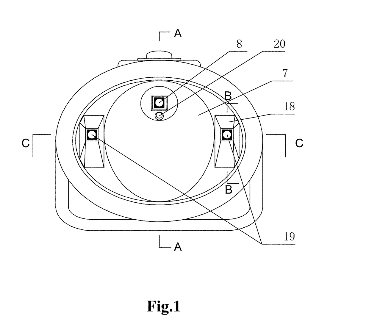
[0050]As shown in FIG. 1, the mining lamp with uniform auxiliary lights comprises a housing, a main light source 8, two auxiliary light sources 19, a main lamp cup 7, and two auxiliary lamp cups 18. The main light cup 7 and the two auxiliary lamp cups 18 are arranged in the housing. The main light source 8 is accommodated in the main lamp cup 7, and the two auxiliary light sources 19 are respectively accommodated in the two auxiliary lamp cups 18. The two auxiliary light sources 19 are symmetrically located on the left and the right sides of the main light source 8 but not in the same line with the main light source 8.

[0051]The side wall of the auxiliary lamp cup 18 has a reflecting effect, and the reflecting surfaces are flat surfaces, and the side wall is in the form of a rearward tapering horn. It is preferable that the auxiliary lamp cup 18 is enclosed by a plurality of flat reflecting surfaces arranged one after another. It is further preferable that said plurality of flat refl...

embodiment 2

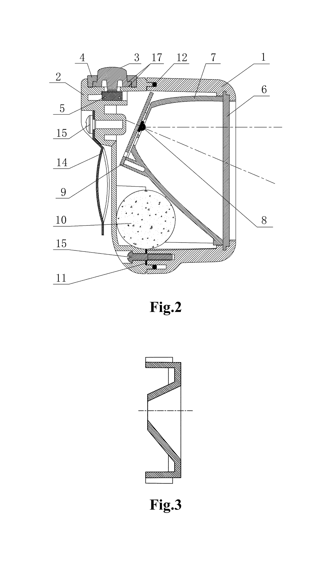
[0055]As shown in FIG. 3, as a specific embodiment of the present invention, based on the wearable mining lamp described in the first embodiment, the angle between the front end face of the auxiliary lamp cup and the optical axis of the auxiliary light source is 87° to 91°, so that the auxiliary lamp irradiates with an approximately horizontal optical axis.

[0056]In such design, it is unnecessary to arrange the auxiliary lamp cup with inclination in the housing, which can reduce the space occupation inside the mining lamp to the uttermost, and facilitate the installation of the auxiliary lamp cup and other components, such as the circuit board and the front cover, of the mining lamp, as well as the connection there between.

[0057]Since the wearable mining lamp is usually worn on a safety helmet, the auxiliary lamp irradiates with an approximately horizontal optical axis, so that the light path of the auxiliary lights lies higher than the sight of the user and runs parallel thereto, as...

embodiment 3

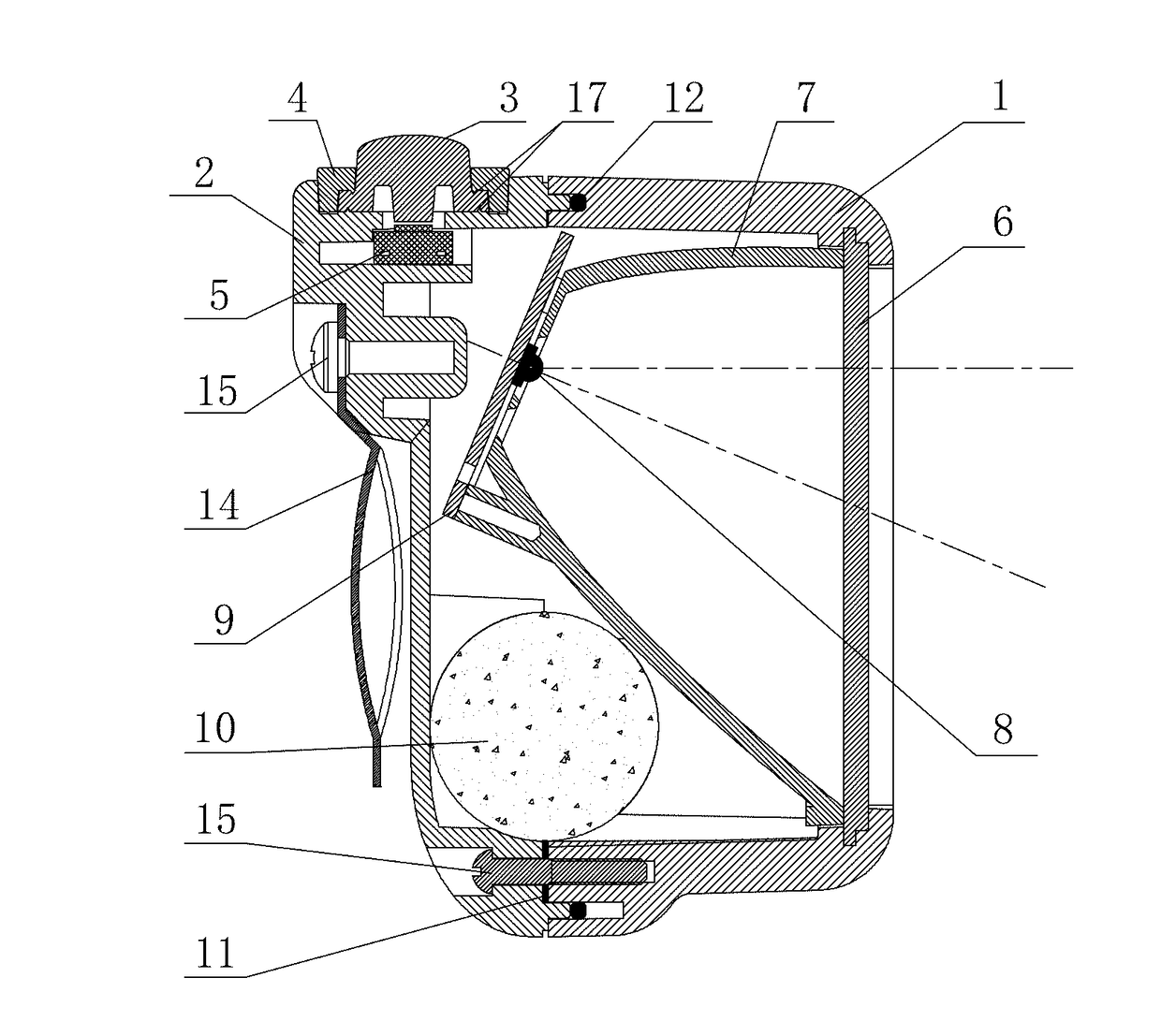
[0061]As shown in FIG. 2, as another embodiment of the present invention, the main lamp cup 7 of the wearable mining lamp described in the first or second embodiment is arranged in the housing with inclination, so that the angle between the optical axis of the main lamp cup and the front end face of the main lamp cup is 65° to 69°.

[0062]A wearable mining lamp is usually inserted and hung on a safety helmet and worn on the head. The main light source forms an optical axis of main light irradiation by the condensing effect of the lamp cup. If the main light also irradiates with a horizontal optical axis, the light path of the main light will also lie higher than the sight of the user and runs parallel thereto, as a result, the area illuminated with the main light formed before the eyes of a user lies higher than the sight of the user, causing the asynchronization between the area illuminated with the main light and the horizontal sight of the user. In order to make the illumination po...


PUM


Abstract

The present invention relates to a wearable mining lamp with uniform auxiliary lights, comprising a main light source and a main lamp cup. The mining lamp further comprises auxiliary light sources and auxiliary lamp cups for mounting the auxiliary light sources; the side wall of the auxiliary lamp cup has a reflecting effect, the reflecting surfaces are flat surfaces, and the side wall is in the form of a rearward tapering horn. The miniature lamp cup structure disclosed by the present invention can regulate the low-beam projection in a predefined area to provide uniform illumination without light spots and shadow interferences, so as to provide a high-quality illumination environment for low-beam operation and meet the requirements of close-range observation or operation.

Description

FIELD OF THE INVENTION[0001]The present invention relates to an illumination technology or a mining lamp, in particular a wearable mining lamp with uniform auxiliary lights.BACKGROUND OF THE INVENTION[0002]Wearable mining lamps mainly provide high-beam condensing illumination, but in the operation with the use of wearable mining lamps, the utilization probability of low beams is over 80%. Since the existing mining lamps are not assisted with suitable low-beam lamps, high-beam lamps are usually used as low-beam lamps for illumination. However, due to the small lighting area and the presence of shadow interference, the illumination is not uniform. As a result, the overall illumination effect during the operation is unsatisfied. Light spots with high illuminance of focused high-beam will cause glaring effect and discomfort in the eyes of user, which negatively influences work efficiency. The improvement in the fining degree of maintenance or operation of equipments put forward higher r...

Claims


Application Information

Patent Timeline
Patent Type & Authority Applications(United States)
IPC IPC(8): F21V7/00F21V31/00F21V23/04F21V7/04F21L4/08
CPCF21V7/0075F21V7/04F21Y2115/10F21V23/0414F21V31/005F21L4/08F21L4/027F21V7/10F21V19/001F21L4/02
Inventor WANG, HONGHUAWANG, CHUNHUAYU, LIANGKEWAN, CHENGBO
Owner WUHAN KINYUN SCI & TECH
Why Eureka
Try Eureka