
Texture space shading and reconstruction for ray tracing

a technology of texture space and reconstruction, applied in the field of computer processors, can solve the problems of noisy images, high memory, computation, power, etc., and achieve the effects of fast rendering, noisy images, and expensive ray tracing techniques

Active Publication Date: 2017-07-20
INTEL CORP
View PDF6 Cites 18 Cited by
  • Summary
  • Abstract
  • Description
  • Claims
  • Application Information

AI Technical Summary

Benefits of technology

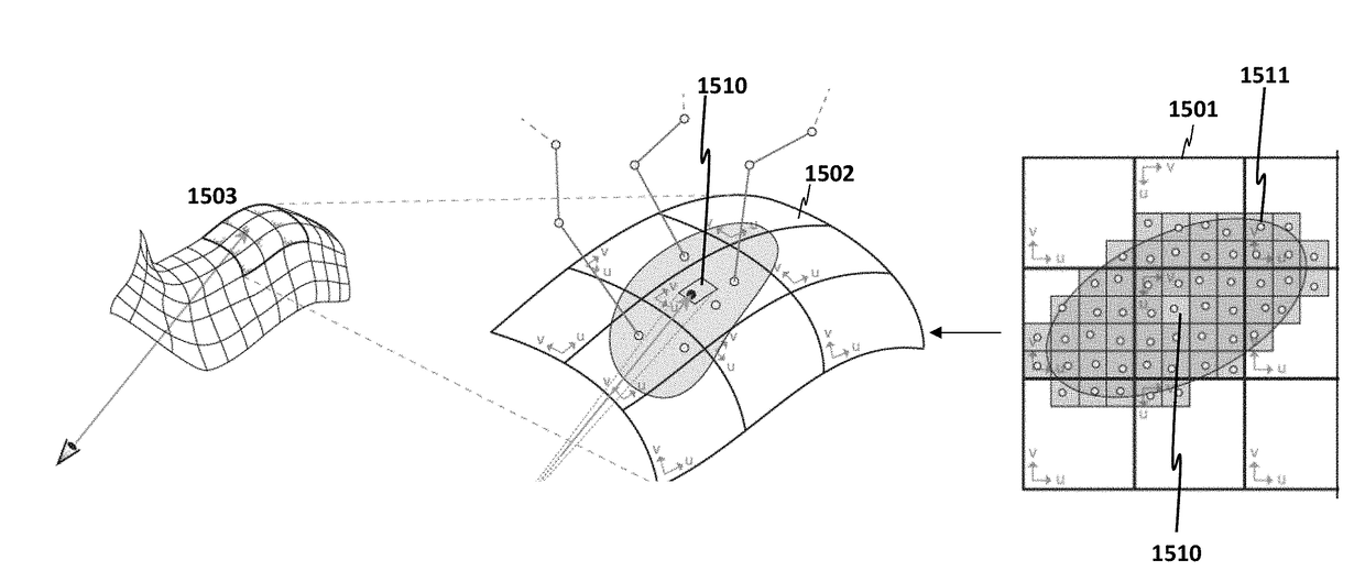
This patent describes a new approach for filtering and shading in ray tracing, which is a technique used for generating realistic images in computer graphics. The approach is designed to be more efficient and effective in filtering and shading, with the ability to handle camera effects and limited memory footprint. The invention is based on a novel approach for sampling and filtering, which allows for more efficient implementation, reuse of results, limited memory footprint, and separate handling of camera effects. The approach can be used for real-time previsualization of ray traced scenes or in future hardware / software on GPUs.

Problems solved by technology

Ray tracing can generate extremely realistic images, but ray tracing techniques are costly in memory, computations, and power since billions of rays need to be traced and shaded to render a single image.
With an insufficient number of rays, rendering is faster but the images are noisy due to the random nature of the sampling.
High-quality real-time ray tracing cannot realistically become a reality until such denoising filters are efficient enough for real-time implementations on graphics processing units (GPUs) or central processing units (CPUs).
However, existing techniques take seconds, or even minutes per frame, and typically require several full-screen auxiliary buffers to guide the reconstruction process.
In addition, due to an underlying assumption of noise-free guide images, these approaches struggle with camera effects such as defocus and motion blur.
Another challenge for image-space filters is visibility discontinuities, which occur, for example, at object boundaries where samples from the foreground and background mix.
A lot of the complexity in existing filters comes from trying to filter across such discontinuities while preserving sharp edges and other image features.
However, these methods require complex data structures and expensive queries (e.g. kNN-searches) to locate nearby samples in large 3D data sets.
With today's fast ray tracers such as Intel's Embree and NVIDIA's OptiX, and emerging hardware ray tracing on the horizon, reasonably complex scenes can be rendered in real time; however, only at very limited sampling budgets (e.g. 8 or 16 primary rays per pixel).

Method used


Image

  • Texture space shading and reconstruction for ray tracing
  • Texture space shading and reconstruction for ray tracing
  • Texture space shading and reconstruction for ray tracing

Examples


Embodiment Construction

[0031]In the following description, for the purposes of explanation, numerous specific details are set forth in order to provide a thorough understanding of the embodiments of the invention described below. It will be apparent, however, to one skilled in the art that the embodiments of the invention may be practiced without some of these specific details. In other instances, well-known structures and devices are shown in block diagram form to avoid obscuring the underlying principles of the embodiments of the invention.

Exemplary Graphics Processor Architectures and Data Types

[0032]System Overview

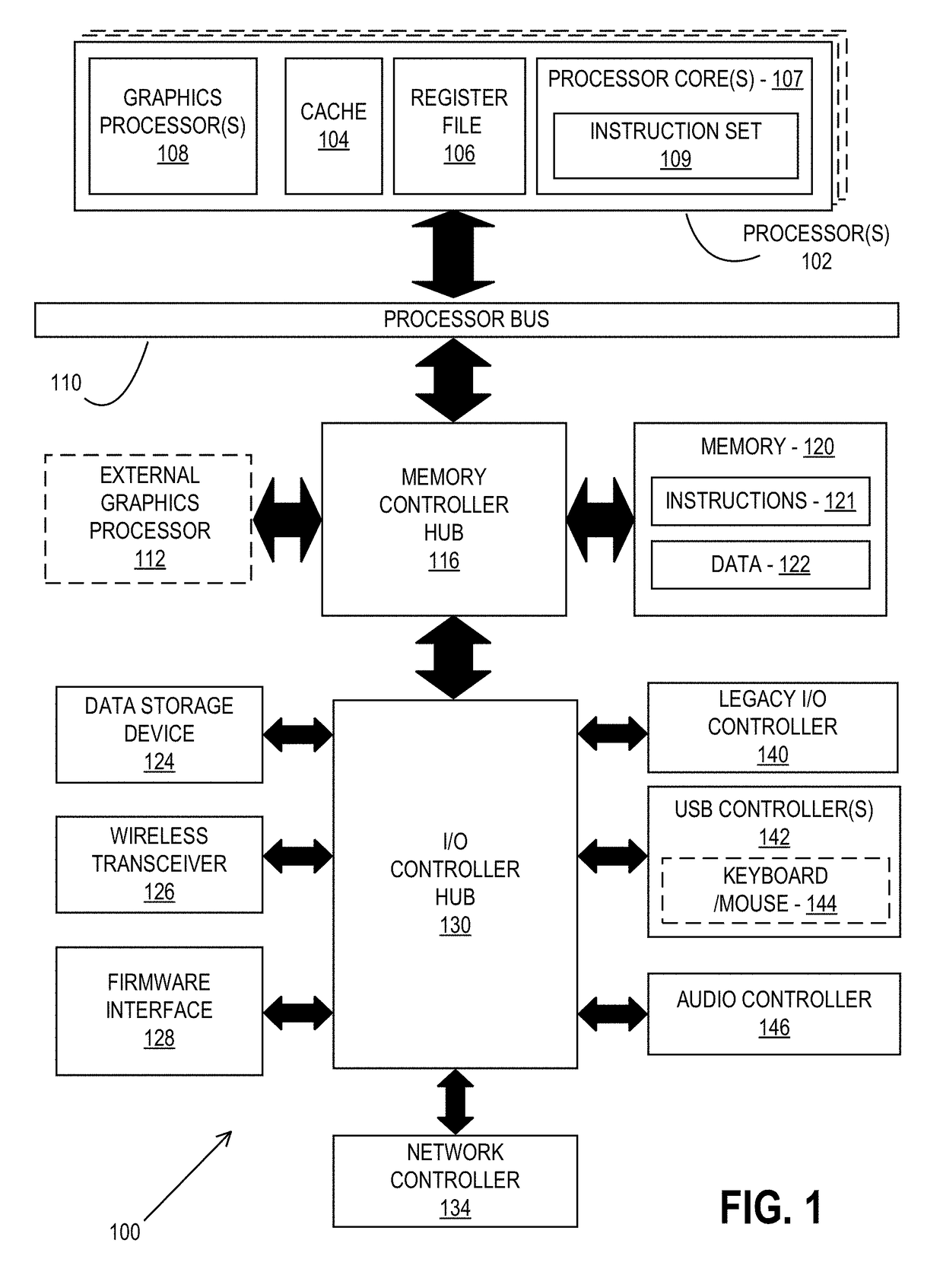
[0033]FIG. 1 is a block diagram of a processing system 100, according to an embodiment. In various embodiments the system 100 includes one or more processors 102 and one or more graphics processors 108, and may be a single processor desktop system, a multiprocessor workstation system, or a server system having a large number of processors 102 or processor cores 107. In on embodiment, the sys...


PUM


Abstract

An apparatus and method are described for texture space shading. For example, one embodiment of a method comprises: performing texture mapping to map one or more textures to surfaces of one or more objects in texture space within a ray tracing architecture; and performing sampling and reconstruction directly on the surfaces of the objects in the texture space.

Description

CROSS REFERENCE TO RELATED APPLICATIONS[0001]This application is related to and claims the benefit of U.S. Provisional Application Ser. No. 62 / 279,589, filed, Jan. 15, 2016, entitled “Texture Space Shading And Reconstruction For Ray Tracing”, by which is hereby incorporated by reference herein in its entirety.BACKGROUND[0002]Field of the Invention[0003]This invention relates generally to the field of computer processors. More particularly, the invention relates to an apparatus and method for texture space shading and reconstruction for ray tracing.[0004]Description of the Related Art[0005]Ray tracing is a graphics processing technique for generating an image by traversing the path of each light ray through pixels in an image plane and simulating the effects of its incidence upon different objects. Following traversal calculations, each ray is typically tested for intersection with some subset of the objects in the scene. Once the nearest object has been identified, the incoming ligh...

Claims


Application Information

Patent Timeline
IPC IPC(8): G06T15/04G06T15/80G06T15/00G06T15/06
CPCG06T15/04G06T15/06G06T2210/36G06T15/005G06T15/80
Inventor MUNKBERG, CARL J.HASSELGREN, JON N.CLARBERG, FRANZ P.ANDERSSON, MAGNUSTOTH, ROBERT M.NILSSON, JIM K.AKENINE-MOLLER, TOMAS G.
Owner INTEL CORP
Learn More