Piezoelectric thin film resonator, filter, and duplexer

a thin film resonator and filter technology, applied in the direction of electrical equipment, impedence networks, etc., can solve the problems of insufficient improvement of q-value and difficulty in sufficiently reducing the leakage of acoustic wave energy

Active Publication Date: 2017-07-20
TAIYO YUDEN KK
View PDF4 Cites 14 Cited by
  • Summary
  • Abstract
  • Description
  • Claims
  • Application Information

AI Technical Summary

Problems solved by technology

However, it is difficult to sufficiently reduce the leak of the acoustic wave energy from the resonance region, and the degree of the improvement of the Q-value is insufficient.

Method used


Image

  • Piezoelectric thin film resonator, filter, and duplexer
  • Piezoelectric thin film resonator, filter, and duplexer
  • Piezoelectric thin film resonator, filter, and duplexer

Examples


first embodiment

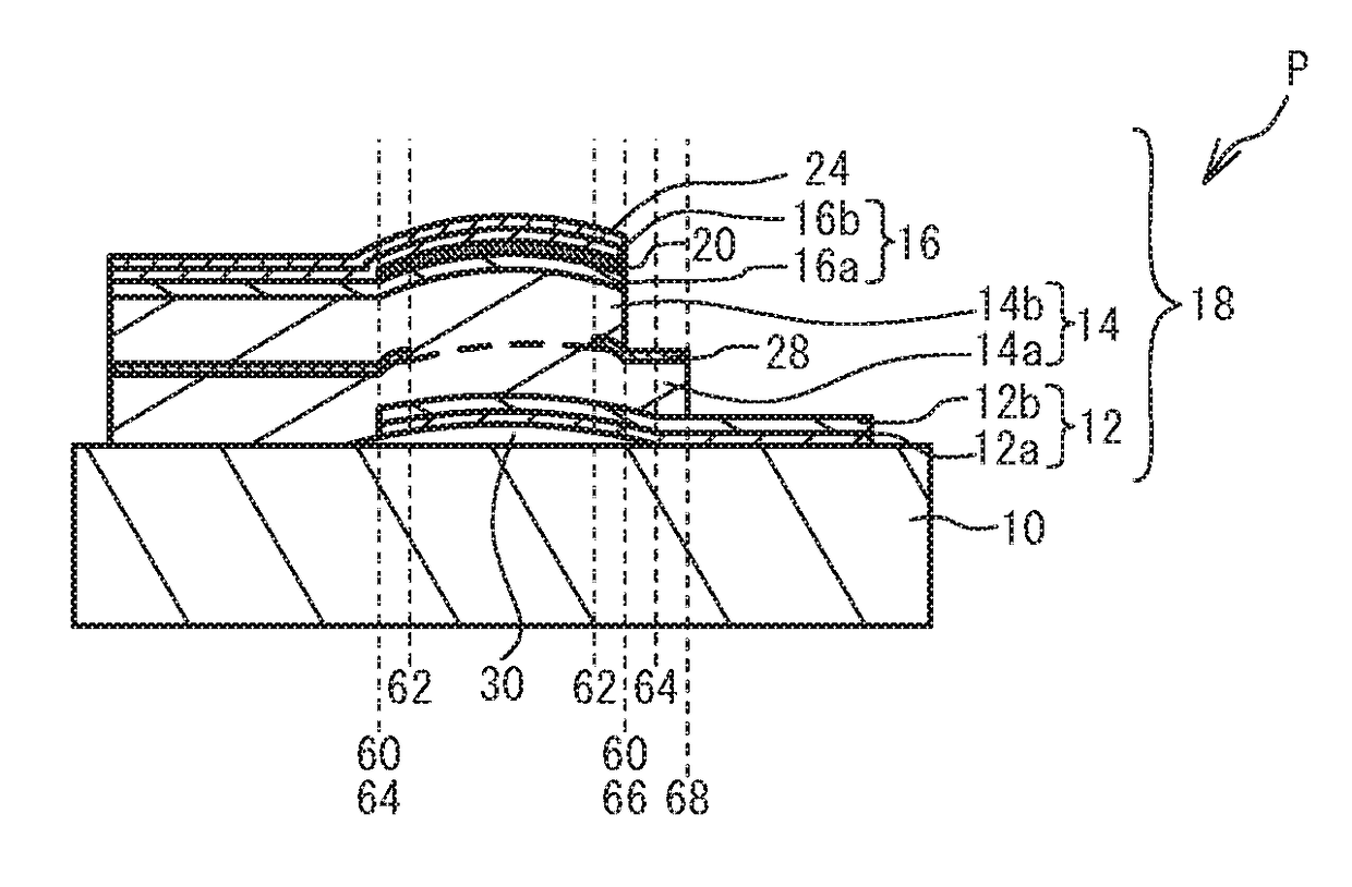
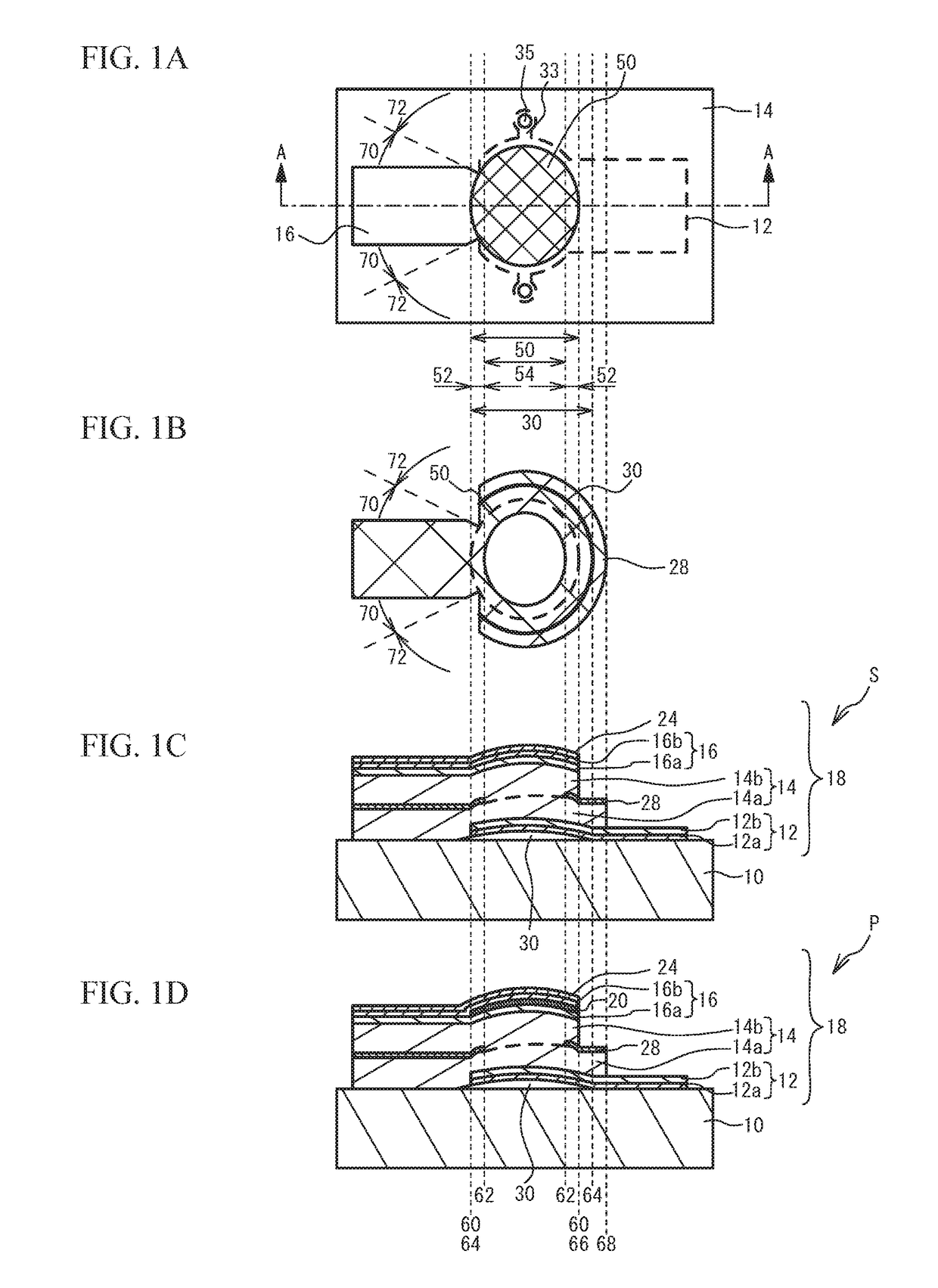
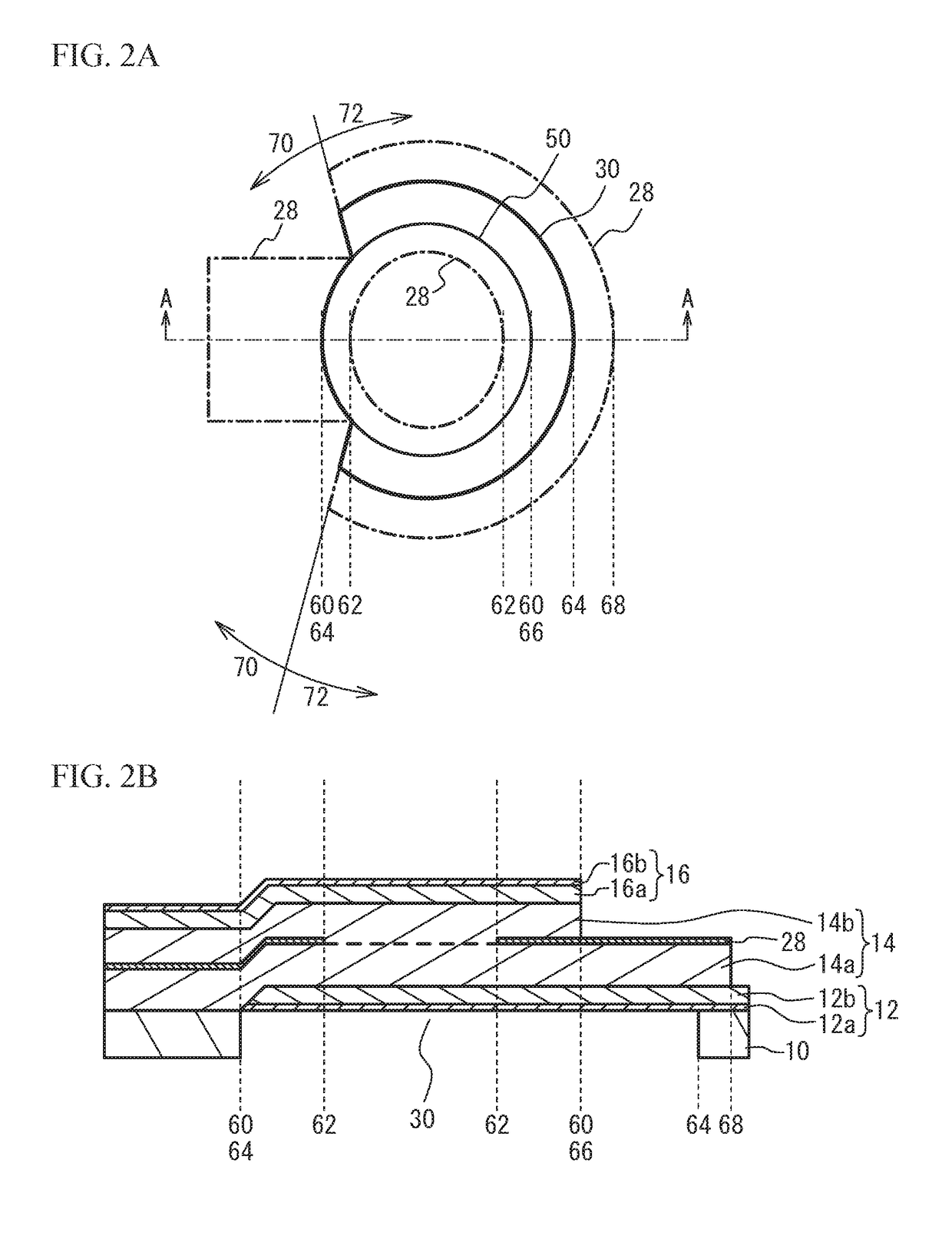
[0031]FIG. 1A is a plan view of a piezoelectric thin film resonator in accordance with a first embodiment, FIG. 1B is a plan view of an insertion film and an air gap, and FIG. 1C and FIG. 1D are cross-sectional views taken along line A-A in FIG. 1A. FIG. 1C illustrates a series resonator of, for example, a ladder-type filter, and FIG. 1D illustrates a parallel resonator of, for example, a ladder-type filter.

[0032]With reference to FIG. 1A and FIG. 1C, the structure of a series resonator S will be described. A lower electrode 12 is located on a substrate 10 that is a silicon (Si) substrate. An air gap 30 having a dome-shaped bulge is formed between the flat principal surface of the substrate 10 and the lower electrode 12. The dome-shaped bulge is a bulge having a shape in which the height of the air gap 30 is large in the periphery of the air gap 30, and increases at distances closer to the center of the air gap 30, for example. The lower electrode 12 includes a lower layer 12a and a...

second embodiment

[0066]A second embodiment and a variation thereof changes the structure of the air gap. FIG. 12A is a cross-sectional view of a piezoelectric thin film resonator of the second embodiment, and FIG. 12B is a cross-sectional view of a piezoelectric thin film resonator of a first variation of the second embodiment. As illustrated in FIG. 12A, a recess is formed in the upper surface of the substrate 10. The lower electrode 12 is flatly formed on the substrate 10. Accordingly, the air gap 30 is formed in the recess of the substrate 10. The air gap 30 is formed so as to include the resonance region 50. Other configurations are the same as those of the first embodiment, and the description is thus omitted. The air gap 30 may be formed so as to penetrate through the substrate 10. An insulating film making contact with the lower surface of the lower electrode 12 may be formed. That is, the air gap 30 may be formed between the substrate 10 and an insulating film making contact with the lower e...

third embodiment

[0101]A third embodiment is an exemplary filter and an exemplary duplexer using the piezoelectric thin film resonator according to any one of the first and second embodiments and the variations thereof. FIG. 19A is a circuit diagram of a filter in accordance with a third embodiment. As illustrated in FIG. 19A, between an input terminal T1 and an output terminal T2, one or more series resonators S1 through S4 are connected in series. Between the input terminal T1 and the output terminal T2, one or more parallel resonators P1 through P4 are connected in parallel. At least one of one or more series resonators S1 through S4 or one or more parallel resonators P1 through P4 may use the acoustic wave resonator in accordance with any one of the first and second embodiments and the variations thereof. The number of resonators in a ladder-type filter can be appropriately selected. The filter including the acoustic wave resonator in accordance with any one of the first and second embodiments a...


PUM


Abstract

A piezoelectric thin film resonator includes: an acoustic reflection layer including an air gap or an acoustic mirror; lower and upper electrodes facing each other in a stacking direction, at least a part of each of the lower and upper electrodes being located on or above the acoustic reflection layer; a piezoelectric film sandwiched between the lower and upper electrodes and including lower and upper piezoelectric films, at least a part of an end face of the piezoelectric film in a film thickness direction being located between outer outlines of the resonance region and the acoustic reflection layer in at least a part of a region surrounding a resonance region; and an insertion film inserted between the lower and upper piezoelectric films, located in at least a part of an outer peripheral region within the resonance region, and not located in a center region of the resonance region.

Description

CROSS-REFERENCE TO RELATED APPLICATION[0001]This application is based upon and claims the benefit of priority of the prior Japanese Patent Application No. 2016-005558, filed on Jan. 14, 2016, the entire contents of which are incorporated herein by reference.FIELD[0002]A certain aspect of the present invention relates to a piezoelectric thin film resonator, a filter, and a duplexer.BACKGROUND[0003]Acoustic wave devices using piezoelectric thin film resonators are used as filters and duplexers of wireless devices such as, for example, mobile phones. The piezoelectric thin film resonator has a structure designed to have a lower electrode and an upper electrode facing each other across a piezoelectric film. The region where the lower electrode and the upper electrode face each other across the piezoelectric film is a resonance region.[0004]Rapid diffusion of wireless systems has promoted the use of many frequency bands. As a result, filters and duplexers have been required to have steep...

Claims


Application Information

Patent Timeline
Patent Type & Authority Applications(United States)
IPC IPC(8): H03H9/17H03H9/70H03H9/56
CPCH03H9/173H03H9/175H03H9/706H03H9/564H03H9/02015H03H9/02118H03H9/174H03H9/568
Inventor LIU, JIANSONGYOKOYAMA, TSUYOSHIKANEKO, HIROOMITANIGUCHI, SHINJINISHIHARA, TOKIHIRO
Owner TAIYO YUDEN KK
Why Eureka
Try Eureka