Sticker, condition monitoring system, method & computer program product

a condition monitoring system and condition monitoring technology, applied in the direction of program control, testing/monitoring control system, instruments, etc., can solve the problems of excessive heat, pressure, friction, and progressive flaking or pitting of the surface of the rolling element and the surface of the corresponding bearing race, and achieve the effect of improving and simpl

Inactive Publication Date: 2017-07-27
AB SKF
View PDF29 Cites 1 Cited by
  • Summary
  • Abstract
  • Description
  • Claims
  • Application Information

AI Technical Summary

Benefits of technology

[0010]An object of the invention is to provide an improved and simple way of monitoring at least one part of at least one machine comprising at least one rotating component.

Problems solved by technology

Rotating components such as bearings or gears are often used in critical applications, wherein their failure in service would result in significant commercial loss to the end-user.
Fatigue failure of a rolling element bearing results from progressive flaking or pitting of the surfaces of the rolling elements and of the surfaces of the corresponding bearing races.
The flaking and pitting may cause seizure of one or more of the rolling elements, which in turn may generate excessive heat, pressure and friction.
However, this type of life prediction is considered inadequate for the purpose of maintenance planning for several reasons.
Another reason is that a bearing's residual life may be radically compromised by short-duration events or unplanned events, such as overloads, lubrication failures, installation errors, etc.
Yet another reason is that, even if nominal operating conditions are accurately reproduced in service, the inherently random character of the fatigue process may give rise to large statistical variations in the actual residual life of substantially identical bearings.
This can however result in long transmission and display times and the data can be difficult to display or interpret.
The transmission, display, storage and interpretation of such data can require a significant amount of energy, time and expertise, and consequently decreases the rate at which measurements and analyses can be made.

Method used


Image

  • Sticker, condition monitoring system, method & computer program product
  • Sticker, condition monitoring system, method & computer program product
  • Sticker, condition monitoring system, method & computer program product

Examples


Embodiment Construction

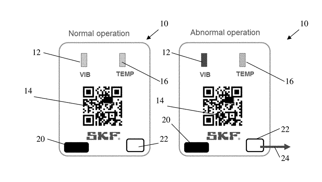
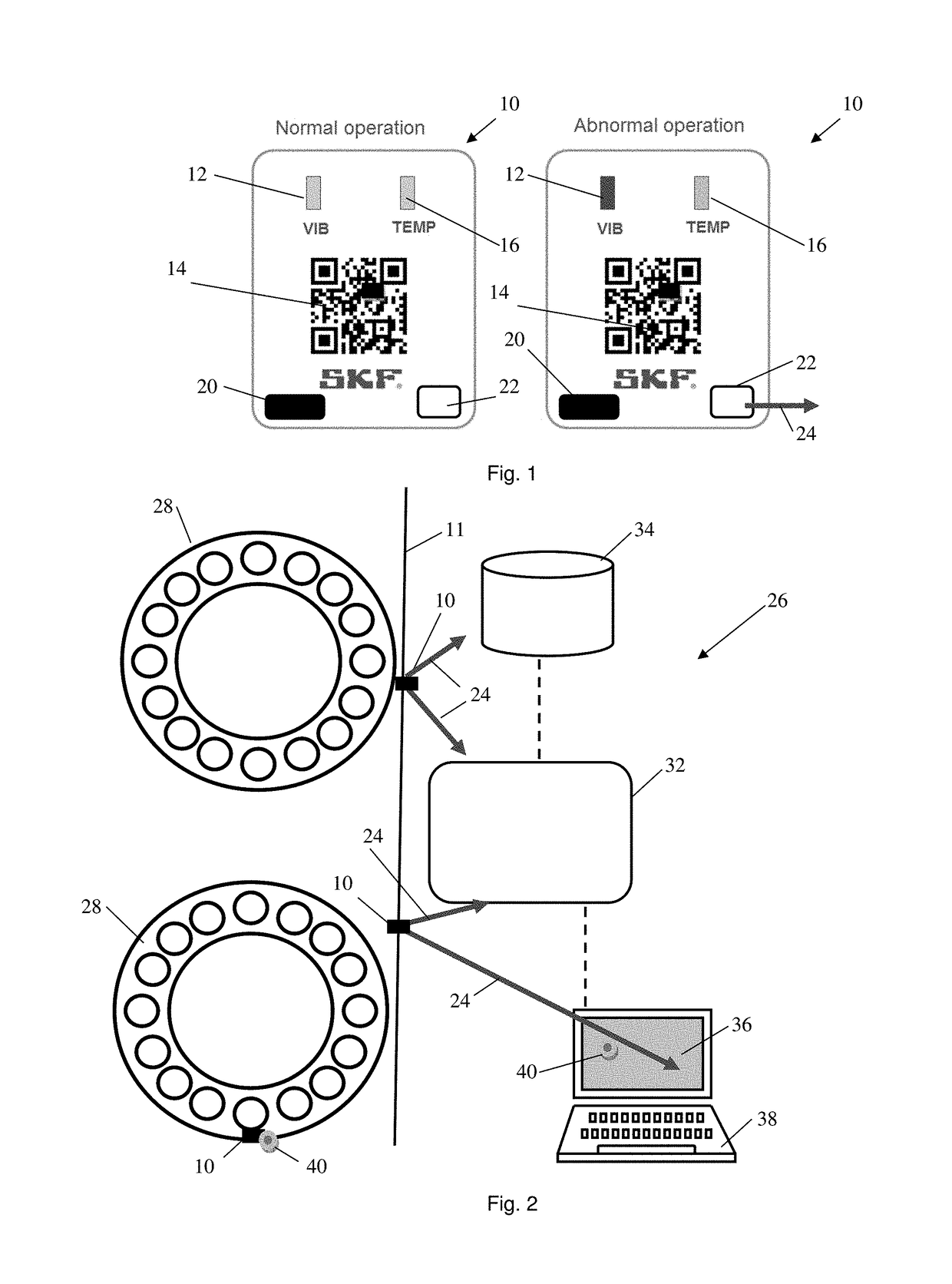
[0039]FIG. 1a) shows a sticker 10 for attaching to at least one part of a machine comprising at least one rotating component that is to be monitored during normal operation of the machine.

[0040]The sticker 10 illustrated in FIG. 1 provides two LEDs labelled “VIB”12 and “TEMP”16, which are arranged to light up or change colour when the vibration or the temperature of the machine comprising at least one rotating component that is being monitored exceeds a predetermined level / value, which predetermined level / value may be changed depending on the machine model, application and / or operating conditions in which the machine is used, whereby the light is detectable to the human eye and / or to a sensor that collects information from the sticker 10. It should be noted that a sticker according to the present invention may provide any type of vibration or temperature indicator and / or any type of vibration or temperature sensor.

[0041]The sticker 10 may provide a paper label having an adhesive at ...


PUM


Abstract

A sticker for attaching to at least one part of a machine having at least one rotating component that is to be monitored. The sticker provides a machine-readable label, such as a Quick Response (QR) code or bar code, which contains information about the component, such as a serial number of the component, and a processor arranged to collect information concerning the use of the at least one rotating component and/or the machine and a transmitter that is arranged to automatically transmit the collected information if/when the processor collects information that a temperature of the at least one part of the machine having at least one rotating component being monitored exceeds a predetermined temperature or a vibration of the at least one part of the machine being monitored exceeds a predetermined level. The transmitted collected information is arranged to be associated with the machine-readable label.

Description

CROSS REFERENCE TO RELATED APPLICATIONS[0001]This application claims priority to Swedish patent application no. 1650074-6 filed on Jan. 22, 2016, the contents of which are fully incorporated herein by reference.FIELD OF THE INVENTION[0002]The present invention concerns a sticker for attaching to at least one part of a machine comprising at least one rotating component that is to be monitored and a condition monitoring system for monitoring at least one machine comprising at least one rotating component, which provides at least one such sticker and a receiver arranged to receive information transmitted from the at least one sticker. The present invention also concerns a method and computer program product for monitoring the condition of at least one machine comprising at least one rotating component.BACKGROUND OF THE INVENTION[0003]Condition monitoring is the process of determining the condition of machines comprising at least one rotating component while the machines are in operatio...

Claims


Application Information

Patent Timeline
Patent Type & Authority Applications(United States)
IPC IPC(8): G06K19/06
CPCG06K19/06028G06K19/06037G05B23/0213G05B2219/24065G01H1/003G01V15/00
Inventor WELIN, ANDERSSTAYKOV, SVETOSLAV
Owner AB SKF
Why Eureka
Try Eureka