Imaging apparatus, imaging system, and control method for imaging apparatus

a control method and imaging technology, applied in the field of imaging apparatus, can solve the problems of deteriorating image quality of stereoscopic images, and achieve the effect of improving image quality

Inactive Publication Date: 2017-07-27
SONY CORP
View PDF6 Cites 4 Cited by
  • Summary
  • Abstract
  • Description
  • Claims
  • Application Information

AI Technical Summary

Benefits of technology

[0011]In accordance with the present technology, it is possible to exert an excellent effect of improving the image quality in the imaging ap...

Problems solved by technology

Thus, there is a problem in that the image quality of the stereoscopic ...

Method used


Image

  • Imaging apparatus, imaging system, and control method for imaging apparatus
  • Imaging apparatus, imaging system, and control method for imaging apparatus
  • Imaging apparatus, imaging system, and control method for imaging apparatus

Examples


first embodiment

1. First Embodiment

[0027][Configuration Example of Imaging System]

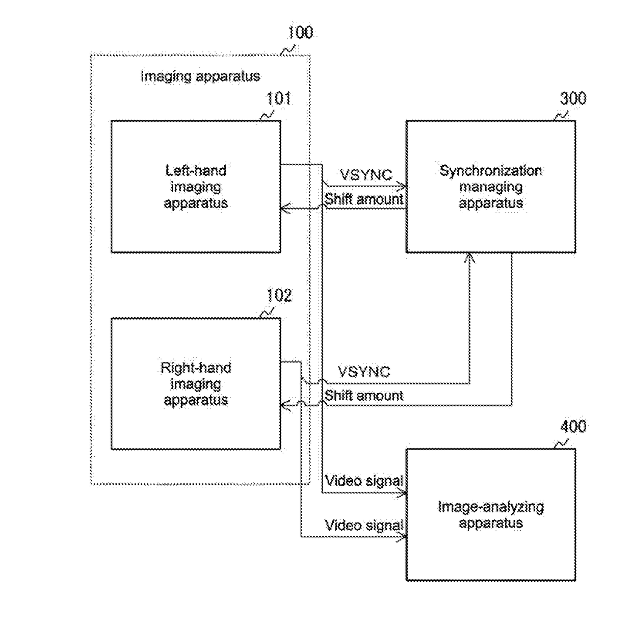
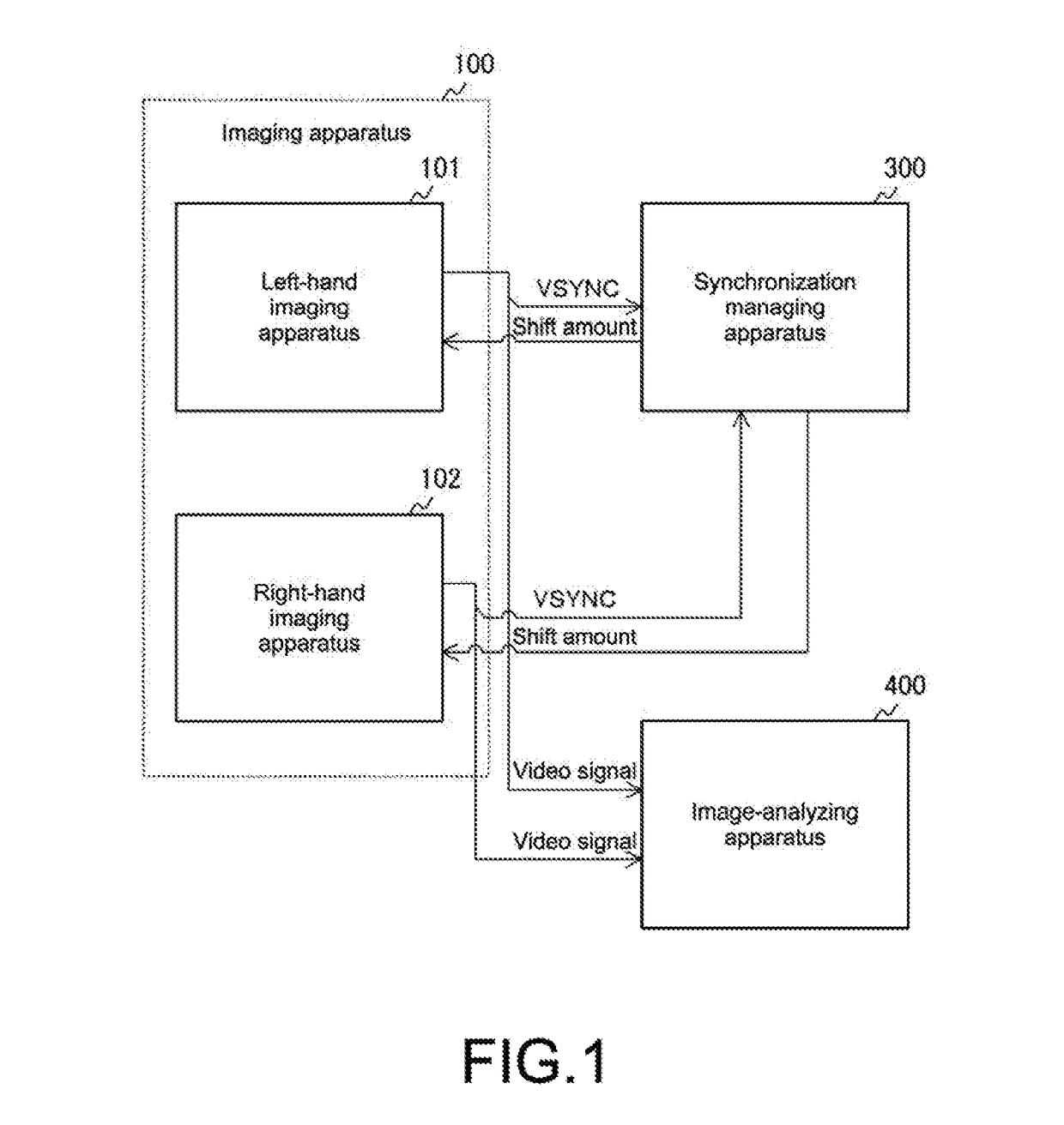
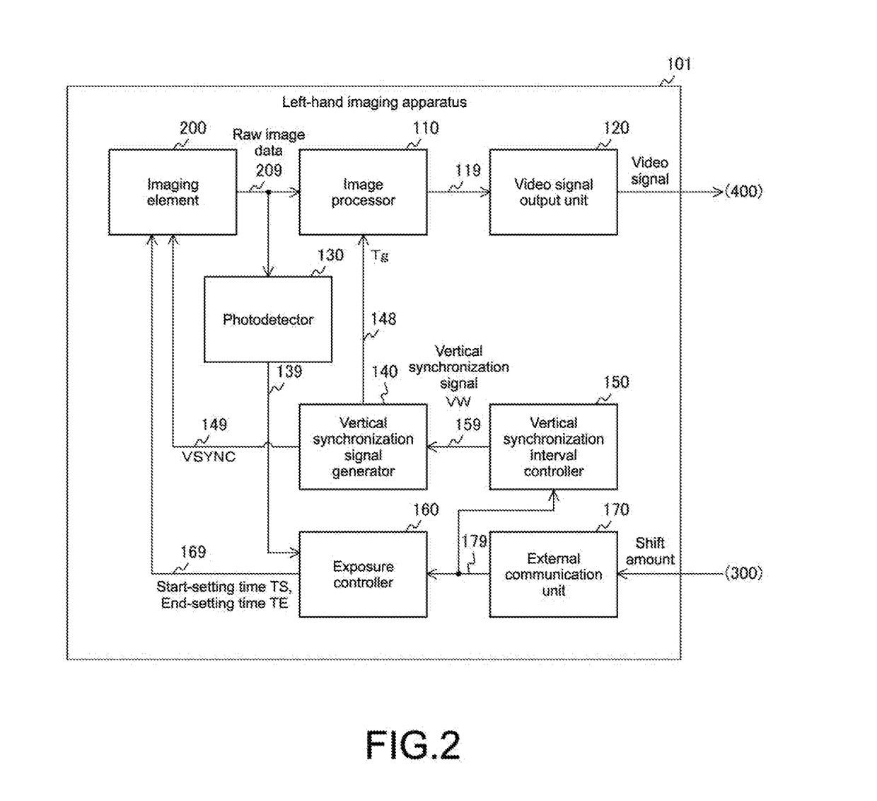
[0028]FIG. 1 is a block diagram showing a configuration example of an imaging system in an embodiment. This imaging system is a system for capturing a stereoscopic image formed of two images and includes a plurality of imaging apparatuses 100 such as a left-hand imaging apparatus 101 and a right-hand imaging apparatus 102, a synchronization managing apparatus 300, and an image-analyzing apparatus 400. Here, an imaging target is an object around an automobile, for example. The left-hand imaging apparatus 101 and the right-hand imaging apparatus 102 are, in the automobile, disposed on the left- and right-hand sides facing the imaging target, respectively. Note that the left-hand imaging apparatus 101 is an example of a first imaging apparatus described in the scope of claims and the right-hand imaging apparatus 102 is an example of a second imaging apparatus described in the scope of claims.

[0029]Although the imaging ap...

second embodiment

2. Second Embodiment

[0088]In the first embodiment, the plurality of imaging apparatuses (e.g., 101 and 102) perform imaging in synchronization with each other. However, a single imaging apparatus may perform imaging in synchronization with the vertical synchronization signal VSYNC. An imaging system according to a second embodiment is different from that of the first embodiment in that the single imaging apparatus performs imaging in synchronization with the vertical synchronization signal VSYNC.

[0089]FIG. 10 is a block diagram showing a configuration example of the imaging system in the second embodiment. This imaging system includes an imaging apparatus 103, a synchronization managing apparatus 301, an image-analyzing apparatus 401, and a position detector 500.

[0090]The imaging apparatus 103 is placed at a predetermined monitoring point near a conveyor belt 510. The conveyor belt 510 moves a plurality of products 520 in a predetermined direction at a constant speed.

[0091]The posit...

third embodiment

3. Third Embodiment

[0094]In the first embodiment, the plurality of imaging apparatuses (101 and 102) perform imaging in synchronization with each other. However, a single binocular imaging apparatus can also be configured to perform imaging. An imaging system according to a third embodiment is different from that of the first embodiment in that the single binocular imaging apparatus performs imaging.

[0095]FIG. 11 is a block diagram showing a configuration example of a binocular imaging apparatus 104 in the third embodiment. This binocular imaging apparatus 104 includes a left-hand imaging unit 105, a right-hand imaging unit 106, a synchronization manager 302, and an image analyzer 402.

[0096]A configuration of the left-hand imaging unit 105 is the same as the left-hand imaging apparatus 101 in the first embodiment. A configuration of the right-hand imaging unit 106 is the same as the left-hand imaging unit 105. A configuration of the synchronization manager 302 is the same as the syn...


PUM


Abstract

To improve the image quality in an imaging apparatus. A synchronization signal generator generates a synchronization signal indicating a synchronization timing for each of synchronization intervals. A synchronization interval controller changes, when an amount of change of the synchronization interval is input, the synchronization interval according to the amount of change. An imaging element generates image data by performing exposure within an exposure period between an exposure start timing when a start-setting time has elapsed from the synchronization timing and an exposure end timing when an end-setting time has elapsed from the synchronization timing after the exposure start timing. An exposure controller changes, when the amount of change is input, at least one of the start-setting time and the end-setting time on the basis of the amount of change.

Description

TECHNICAL FIELD[0001]The present technology relates to an imaging apparatus, an imaging system, and a control method for the imaging apparatus. More particularly, the present technology relates to an imaging apparatus that performs imaging in synchronization with a vertical synchronization signal, an imaging system, and a control method for the imaging apparatus.BACKGROUND ART[0002]Conventionally, in order to monitor a plurality of monitoring points or acquire depth information or stereoscopic images, an imaging system in which imaging is performed by a plurality of imaging apparatuses at the same time has been used. For example, an imaging system in which a stereoscopic image formed of two images is captured by two cameras and a line-of-sight direction as the depth information is detected from the stereoscopic image has been proposed (e.g., see Patent Document 1). In those cameras, imaging timings are synchronized according to a vertical synchronization signal or the like. In gener...

Claims


Application Information

Patent Timeline
IPC IPC(8): H04N13/02H04N5/353H04N5/235H04N13/239
CPCH04N13/0296H04N5/3532H04N5/2353H04N13/0239G03B35/08G03B7/00H04N13/239H04N23/73H04N25/531H04N23/90H04N25/778H04N13/296
Inventor TADANO, RYUICHI
Owner SONY CORP
Why Eureka
Try Eureka