Method for determining a depression state and depression state determination device
- Summary
- Abstract
- Description
- Claims
- Application Information
AI Technical Summary
Benefits of technology
Problems solved by technology
Method used
Image
Examples
first embodiment
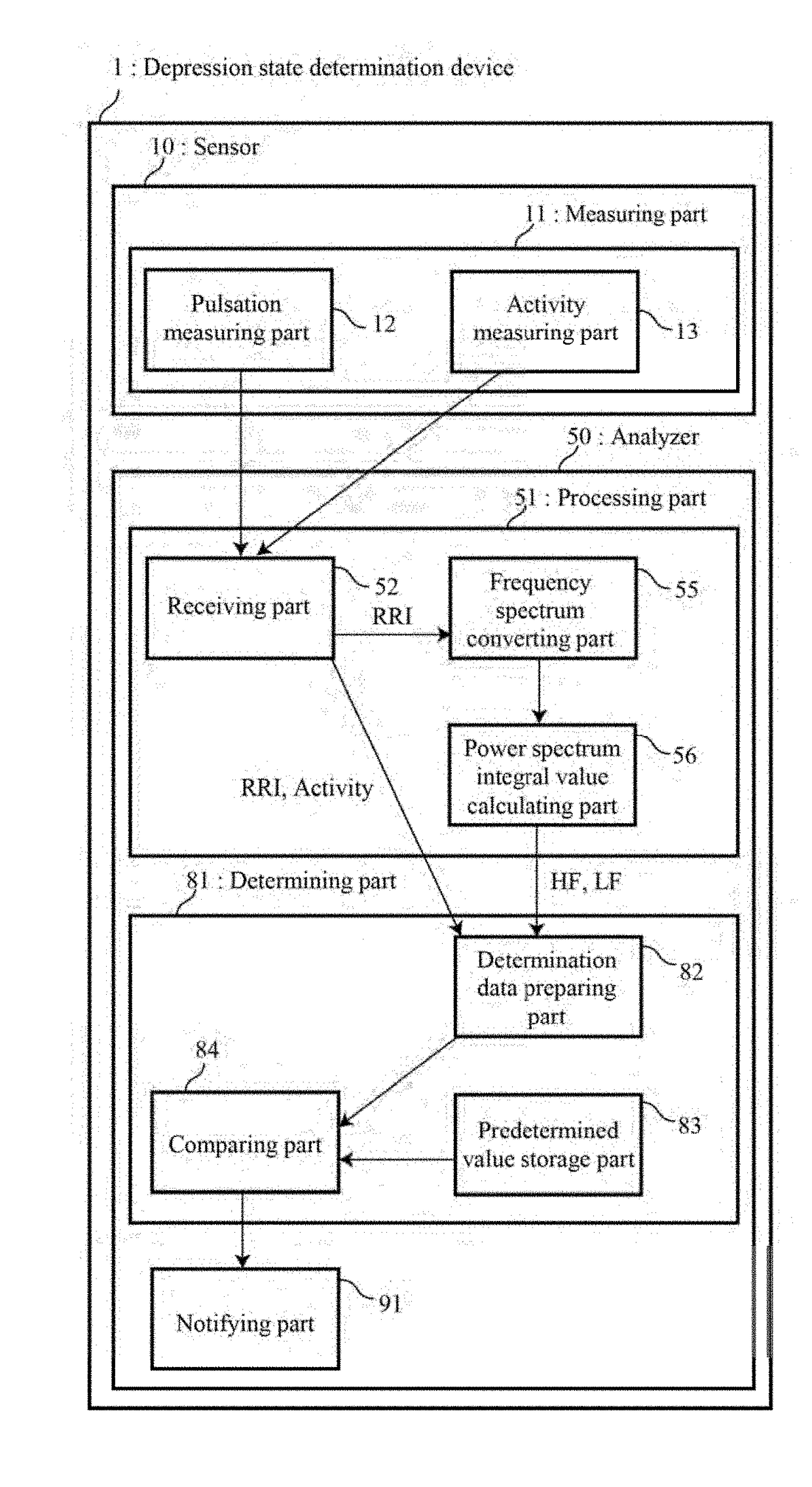
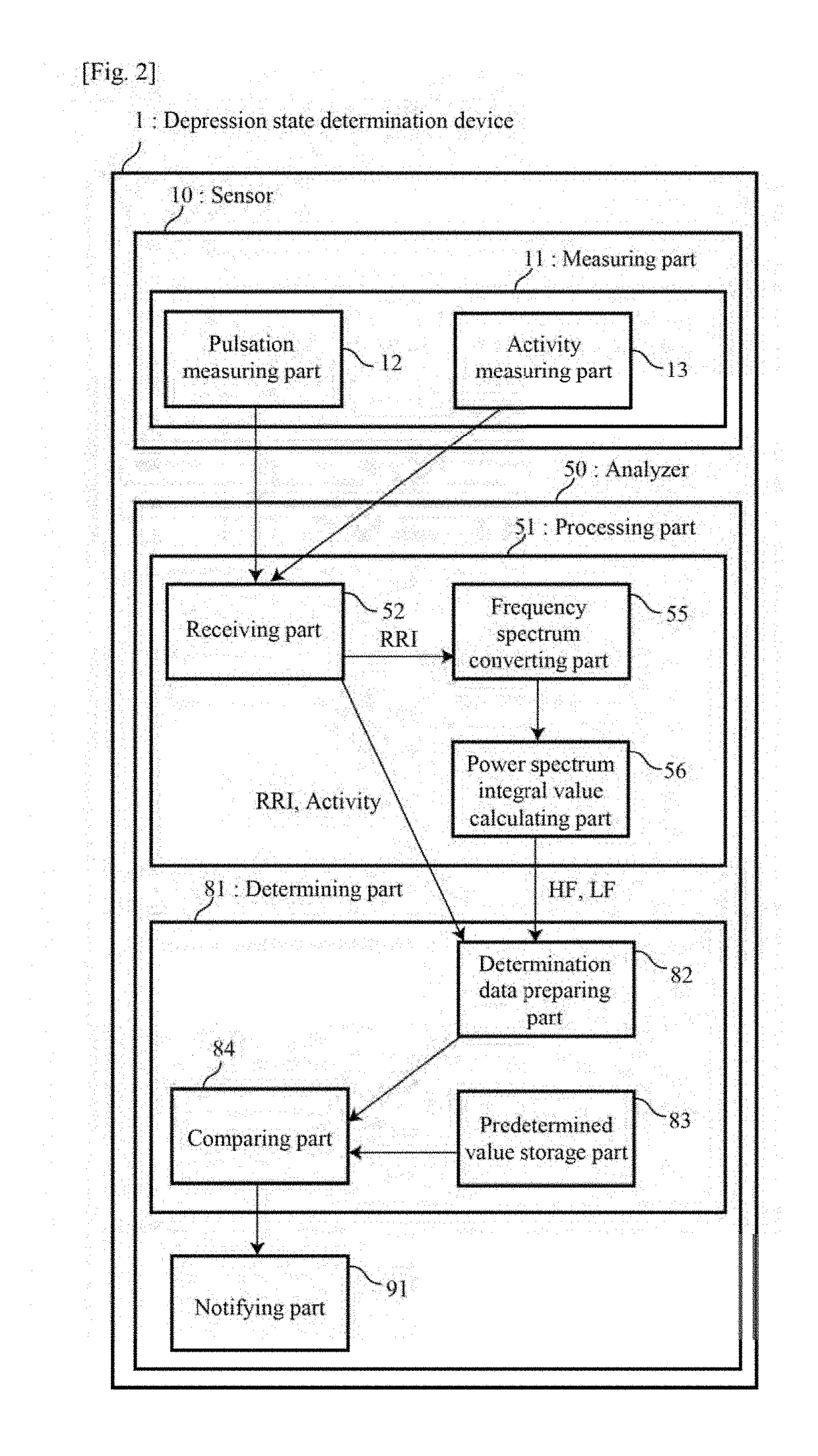
[0107]FIG. 2 is a block diagram showing a configuration of a depression state determination device 1 according to a first embodiment of the present invention. The depression state determination device 1 shown in FIG. 2 includes a sensor 10 as a measuring part and an analyzer 50.
[0108](1) Measuring Part
[0109]The sensor 10 includes a measuring part 11 configured by a pulsation measuring part 12 that detects the pulsation interval, and an activity measuring part 13 that detects the activity. The sensor 10 is small and lightweight, and since the whole body thereof can be attached to skin of the subject in a state where electrodes (not shown) in a body back surface are brought into close contact with a chest of the subject, the sensor 10 is not noticeable because it is concealed under clothes. It is preferred that the pulsation interval is an R-R interval between R waves in an electrocardiographic signal. Since in the R-R interval, a peak of the signal clearly appears, the accuracy of th...
second embodiment
[0125]FIG. 3 is a block diagram showing a configuration of a depression state determination device 2 according to a second embodiment, of the present invention. The depression state determination device 2 shown in FIG. 3 includes a sensor 10 and an analyzer 60. Note that the same components as those of the depression state determination device 1 of the first embodiment are denoted by the same reference signs and a description thereof is omitted.
[0126]The analyzer 60 includes the processing part 61 and a determining part 81, and the processing part 61 includes a receiving part 62, an abnormal data detecting part 63, an abnormal data removal pan 64, a frequency spectrum converting part 65 and a power spectrum integral value 66.
[0127]The abnormal data detecting part 63 decides whether a RRI outputted from the receiving part 62 is to be considered to have an abnormal value. In the second embodiment, an instantaneous heart rate is calculated by multiplying an inverse of a RRI (units of s...
third embodiment
[0131]FIG. 4 is a block diagram showing a configuration of a depression state determination device 3 according to a third embodiment of the present invention. The depression state determination device 3 shown in FIG. 4 includes a sensor 20 and an analyzer 50. Note that the same components as those of the depression state determination device 1 of the first embodiment are denoted by the same reference signs and a description thereof is omitted.
[0132]A measuring part 21 of the sensor 20 is preferably provided with an input means 24 that inputs an awaking state or a sleeping state in addition to a pulsation measuring part 22 and an activity measuring part 23. Thereby, a subject operates the input means 24 by himself or herself at the start time of an awaking time zone and at the start time of a sleeping time zone, which can bring about awaking information and sleeping information. The input means 24 is, for example, a switch provided in a surface of the sensor, and this switch may be o...
PUM
 Abstract
Description
Claims
Application Information
 - R&D
- Intellectual Property
- Life Sciences
- Materials
- Tech Scout
- Unparalleled Data Quality
- Higher Quality Content
- 60% Fewer Hallucinations
Browse by: Latest US Patents, China's latest patents, Technical Efficacy Thesaurus, Application Domain, Technology Topic, Popular Technical Reports.
© 2025 PatSnap. All rights reserved.Legal|Privacy policy|Modern Slavery Act Transparency Statement|Sitemap|About US| Contact US: help@patsnap.com


