Friction stir welding device, friction stir welding system, and friction stir welding method

a friction stir welding and friction stir technology, applied in process control, process control, instruments, etc., can solve the problems of limited application of friction stir welding, and achieve the effects of enhancing machining accuracy, reducing the cost of the fsw device as a whole, and improving the positioning accuracy of the machining tool

Inactive Publication Date: 2017-08-03
HONDA MOTOR CO LTD
View PDF6 Cites 6 Cited by
  • Summary
  • Abstract
  • Description
  • Claims
  • Application Information

AI Technical Summary

Benefits of technology

[0009]The support member may include an articulated arm, and a jig configured to support the machining tool and the rotary drive motor, the support member actuator may include a plurality of arm motors that are provided inside the articulated arm, and the jig may be attached to a distal end of the articulated arm. Owing to this feature, as a portion of the FSW device, it becomes possible to utilize a general-purpose articulated arm, whereby the cost of the FSW device as a whole can be reduced.
[0010]In the case that the jig is a C-shaped member, the machining tool and the rotary drive motor may be disposed on one end side of the C-shaped member, and a guided member may be disposed on another end side of the C-shaped member, the guided member being guided by a guide member formed on a welded member support unit configured to support the first member to be welded and the second member to be welded. In accordance with the above, the positioning accuracy of the machining tool can be improved by combining the rotary drive motor, the guide member, and the guided member, and it is possible to enhance machining accuracy.
[0011]Further, from the fact that the jig is a C-shaped member, the rotary drive motor is arranged face-to-face with the guide member and the guided member across the boundary between the first member to be welded and the second member to be welded. For this reason, a portion of the force from the rotary drive motor or the support member actuator is received in the guide member, the guided member, and the jig. Therefore, it is possible to reduce the size or to lower the cost of th

Problems solved by technology

With the spot welding system 10 of JP2003-205374A, since spot welding is performed, the system is not necessarily suitable for appli

Method used


Image

  • Friction stir welding device, friction stir welding system, and friction stir welding method
  • Friction stir welding device, friction stir welding system, and friction stir welding method
  • Friction stir welding device, friction stir welding system, and friction stir welding method

Examples


embodiment

A. Embodiment

A1. Configuration of Friction Stir Welding System 10

(A1-1. Overall Configuration)

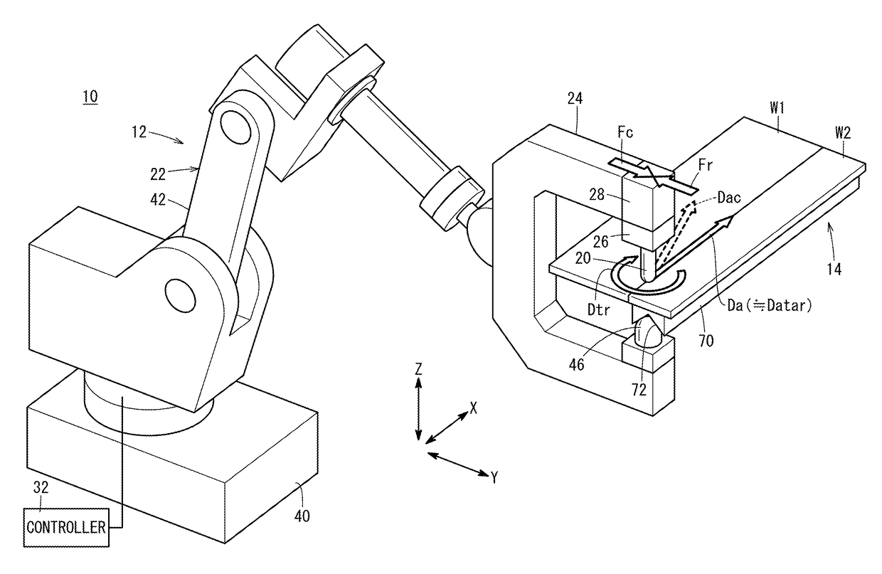
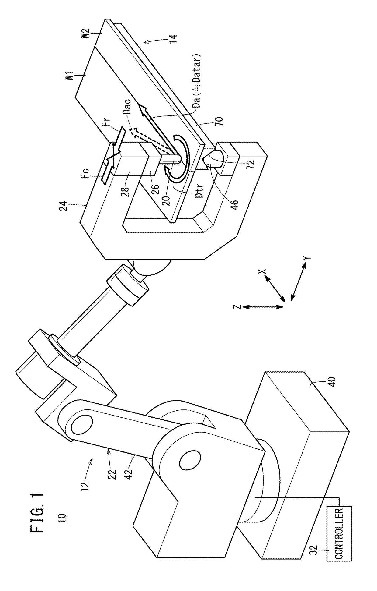
[0024]FIG. 1 is an external view showing in a simplified manner the external appearance of a friction stir welding system 10 (hereinafter referred to as an “FSW system 10”) according to an embodiment of the present invention. The FSW system 10 is equipped with a friction stir welding device 12 (hereinafter referred to as an “FSW device 12”) and a welded member support unit 14 (hereinafter also referred to as a “support unit 14”).

(A1-2. FSW Device 12)

(A1-2-1. Overall Composition of FSW Device 12)

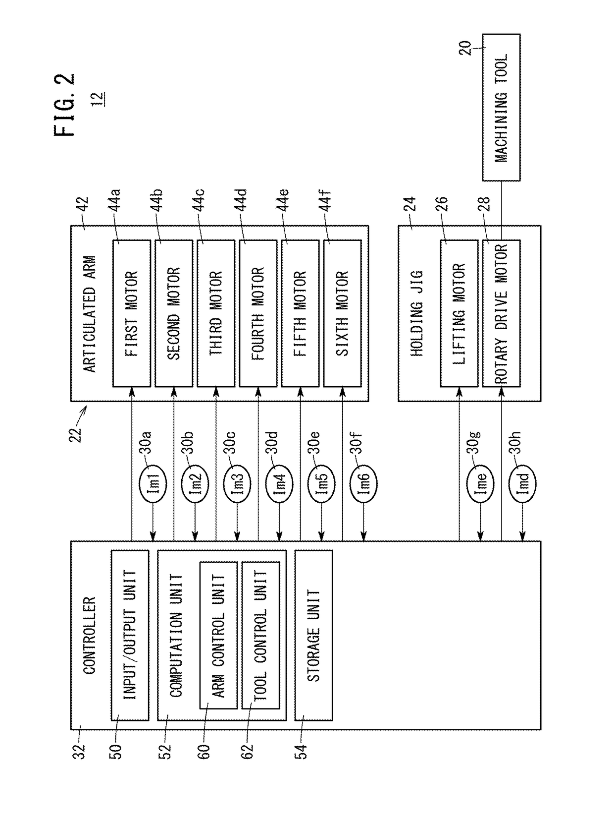
[0025]FIG. 2 is a block diagram showing in a simplified manner the configuration of the FSW device 12 according to the present embodiment. The FSW device 12 carries out FSW (friction stir welding) with respect to a first member to be welded W1 (hereinafter also referred to as a “first workpiece W1” or a “workpiece W1”) and a second member to be welded W2 (hereinafter also referred to as a “second wor...


PUM

PropertyMeasurementUnit
Forceaaaaaaaaaa

Abstract

Provided are a friction stir welding (FSW) device, FSW system, and FSW method with which it is possible to expand the applications of FSW while increasing processing accuracy. In a FSW device, when a first member to be welded and a second member to be welded are continuously welded by moving a processing tool in a linear or curved manner with the processing tool, while rotating, being pressed in the axial direction against the first member to be welded and the second member to be welded, a control device executes a reaction force correction control that controls the output of support member actuators so as to cancel the reaction force acting upon the processing tool as a result of the rotation of the processing tool.

Description

TECHNICAL FIELD[0001]The present invention relates to a friction stir welding device, a friction stir welding system, and a friction stir welding method for continuously welding together a first member to be welded and a second member to be welded by moving a machining tool linearly or curvilinearly.BACKGROUND ART[0002]A spot welding system 10 for spot welding members to be welded by friction stir welding (FSW) has been disclosed in Japanese Laid-Open Patent Publication No. 2003-205374 (hereinafter referred to as “JP2003-205374A”) (abstract, paragraph [0001]). The spot welding system 10 is made up from an articulated robot 11, an FSW head 12 attached to a distal end of a robot arm, a surface plate 13 that retains a workpiece W horizontally, and a controller 14. A welding tool 15 and a fixing device 16 are mounted on the FSW head 12. The fixing device 16 includes a cylindrical pressing member 19 and a spring 18. At the time of welding, the pressing member 19 is pressed against a surf...

Claims


Application Information

Patent Timeline
IPC IPC(8): B23K20/12B25J9/16
CPCB23K20/123B23K20/1245G05B2219/45146B25J9/1633B23K20/125B25J11/005
Inventor SAYAMA, MITSURUODA, MASARUFURUYA, YOSHITAKE
Owner HONDA MOTOR CO LTD
Why Eureka
Try Eureka