
Separating Components of a Pocket Sprung Mattress Sub-Assembly

a technology for separating components and mattresses, applied in the direction of upholstery auxiliaries, grain treatments, manufacturing tools, etc., can solve the problems of high-grade cutting blades, difficult manual handling of springs, and present dangerous sharp edges

Active Publication Date: 2017-08-03
THE FURNITURE RECYCLING GRP LTD
View PDF5 Cites 7 Cited by
  • Summary
  • Abstract
  • Description
  • Claims
  • Application Information

AI Technical Summary

Benefits of technology

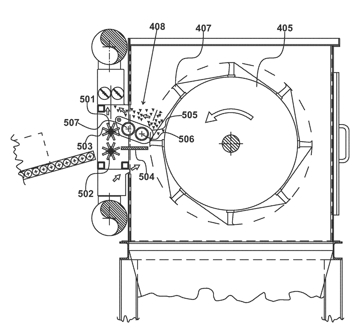
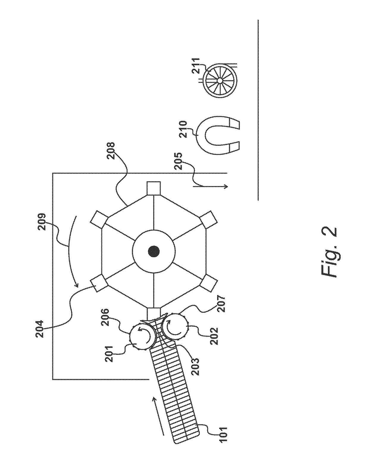
The technical effect of this patent is an apparatus and method for separating components of a pocket-sprung-mattress sub-assembly. The apparatus includes a rotating tearing drum with a plurality of tearing devices that pull metal springs from the sub-assembly. A drive motor rotates the tearing drum, and a feeding assembly compresses the end portion of the sub-assembly and moves it into contact with the tearing devices. The feeding assembly includes a first feed roller and a second feed roller with protrusions for gripping the sub-assembly. An anvil plate is positioned between the rotating drum and the feed rollers to support the end portion of the sub-assembly while the tearing devices pull the springs out of the sub-assembly. The method involves compressing the end portion of the sub-assembly, feeding it towards the tearing devices, piercing the pockets with the tearing devices, pulling out individual springs, and releasing them for collection.

Problems solved by technology

The manual handling of springs is difficult, given that their movements are somewhat unpredictable and when exposed, they tend to present dangerous sharp edges.
A problem with this known approach is that very high grade cutting blades are required in order to cut through the spring steel present within the mattresses.
Even high grade cutting blades, including carbide laminates, will degrade and require replacement, thereby increasing overall running costs.
The equipment itself tends to be expensive, replacement of worn parts becomes expensive and further unpredictable costs are often involved during periods when the machine cannot actually be operated; due to the presence of a jam or due to routine repair.
Consequently, machines of this type tend to be uneconomic for recycling mattresses containing pocket springs or the recycling of pocket sprung sub-assemblies.

Method used


Image

  • Separating Components of a Pocket Sprung Mattress Sub-Assembly
  • Separating Components of a Pocket Sprung Mattress Sub-Assembly
  • Separating Components of a Pocket Sprung Mattress Sub-Assembly

Examples


Embodiment Construction

FIG. 1

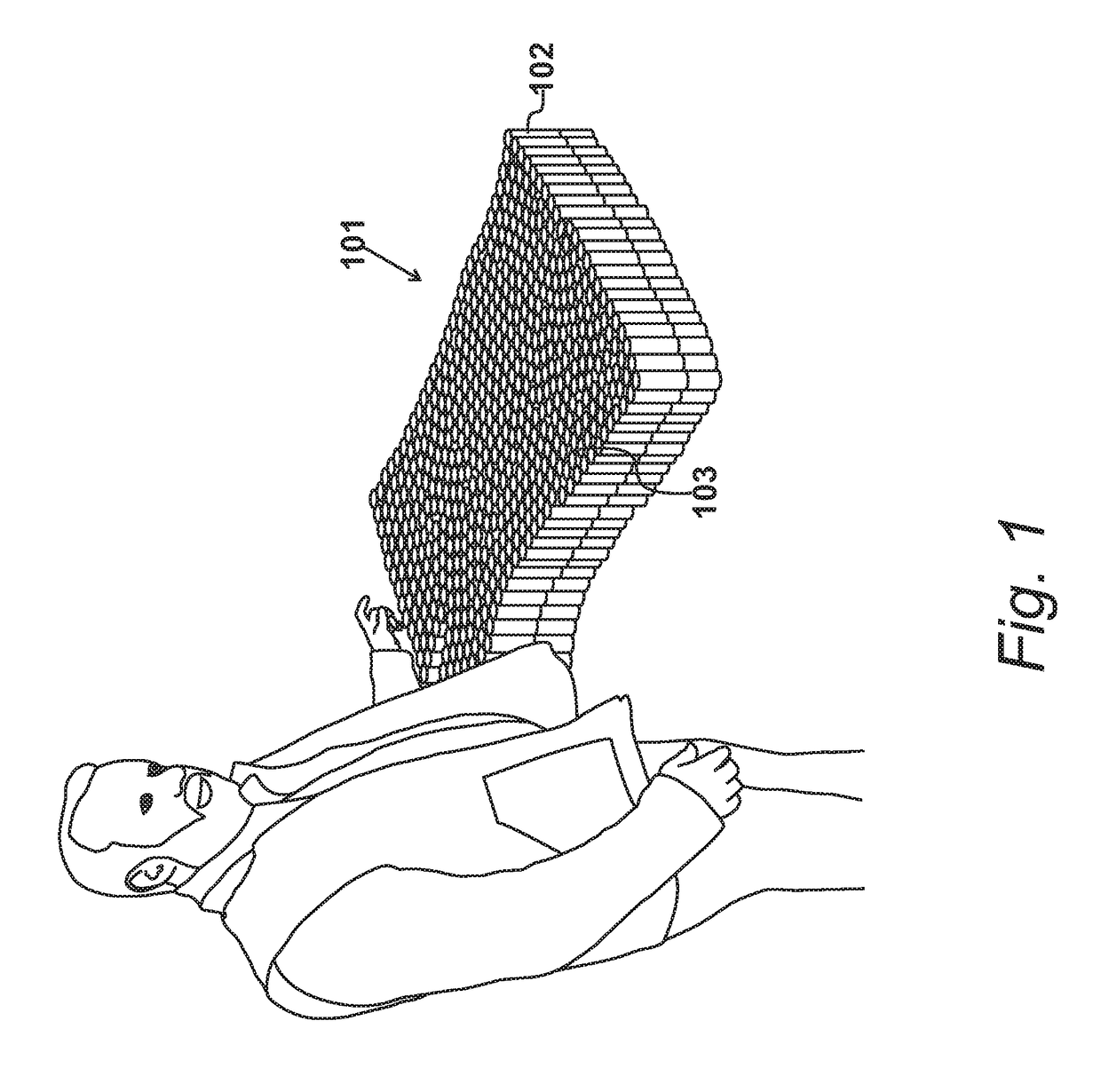
[0017]A pocket-sprung-mattress sub-assembly is shown in FIG. 1. As part of a recycling exercise, components surrounding the sub-assembly, in order to complete the mattress, have been removed. The remaining sub-assembly consists of individual coils 102, each surrounded by a polypropylene or similar material pocket 103. These pockets are in turn glued together on all sides to form the complete spring sub-assembly.

[0018]Assemblies of this type are difficult to recycle, therefore existing recycling operations are uneconomic and it is usual for sub-assemblies of this type be directed toward landfill. It is possible to remove the springs by hand but this is time consuming and dangerous. Furthermore known shredding operations are difficult to implement, given that the steel present within the springs will tend to damage shredding machines, causing the machine to jam when a subsequent batch is introduced. Thus, known automated techniques fail to meet their expectations, in terms of th...


PUM


Abstract

Components of a pocket-sprung-mattress sub-assembly having individual metal springs retained within a matrix of fabric pockets are separated. A rotatable tearing drum 405 is driven by a drive motor 406. Tearing devices 407 are arranged to pull metal springs from a pocket-sprung-mattress sub-assembly during the rotation of the tearing drum 405. A feeding assembly 408 compressors an end portion of the mattress sub-assembly and moves this end portion continually to bring an end of the mattress sub-assembly into contact with the rotating tearing devices 407.

Description

CROSS REFERENCE TO RELATED APPLICATIONS[0001]This application claims priority from United Kingdom patent application No 16 01 978.8, filed Feb. 3, 2016, the entire disclosure of which is incorporated herein by reference in its entirety.BACKGROUND OF THE INVENTION[0002]The present invention relates to an apparatus for separating components of a pocket sprung mattress sub-assembly, in which individual metal springs are retained within a matrix of fabric pockets. The present invention also relates to a method of separating components of a pocket sprung mattress sub-assembly.[0003]It is known to recycle spring-containing mattresses, as described in U.S. Pat. No. 6,016,979. The manual handling of springs is difficult, given that their movements are somewhat unpredictable and when exposed, they tend to present dangerous sharp edges. The system disclosed in the aforesaid United States patent publication performs a cutting and crushing operation to yield spring particles that can be process...

Claims


Application Information

Patent Timeline
IPC IPC(8): B23P19/04A47C27/06
CPCA47C27/064B23P19/048B02C18/06B02C18/2225B02C18/2283B09B3/00B68G15/00B07B15/00B09B5/00B23P19/004
Inventor OETTINGER, NICHOLAS SIMON
Owner THE FURNITURE RECYCLING GRP LTD
Learn More