
Structural element with anticipated prestressing

a structural element and prefabricated technology, applied in the direction of structural elements, building components, floors, etc., can solve the problems of reducing the service life of the structure element, so as to reduce the risk of cracks and less bending. , the effect of less risk

Inactive Publication Date: 2017-08-03
SABBAH ALAIN
View PDF1 Cites 0 Cited by
  • Summary
  • Abstract
  • Description
  • Claims
  • Application Information

AI Technical Summary

Benefits of technology

The patent text describes a method for making a structural element by putting two tensioners under tension while casting the body of the element. The method is easy to implement and can be used to make beams, slabs, and other shapes. The text also describes a way to deactivate the tensioners in the subsequent structure to reduce the pressure and bending on the element's body. The technical effect of the patent text is to provide a simple and effective method for making strong and well-controlled structural elements.

Problems solved by technology

A well-known problem of concrete is that although it is good at withstanding compression forces, it cracks quickly when it is subjected to traction forces.
However, although reinforced concrete presents certain advantages, its use becomes counter-productive when the stresses exerted on the structure become large, as a result of using reinforced concrete of greater section.
In this way, when the concrete is subjected to traction forces, it decompresses, but it never works in traction, thereby avoiding cracks appearing.
However, that method presents two drawbacks.
The first drawback is that when unmolding the beam and releasing the tensioners, said tensioners cause excessive forces on the beam that cause the beam to bend quickly, with the risk of such traction or compression forces generating cracks in the concrete.
Another drawback is that when the beam is not yet loaded, its bending generates traction stresses in the concrete (at the convex face of the beam), and particularly strong localized compression stresses (at the concave face of the beam).
However, that relatively complex technique is generally restricted to large works, since it requires bulky tensioning machines to be used.
Furthermore, it turns out to be expensive, not only because of the use of such machines, but also because the tensioners are passed through special and expensive sheaths in which a special coating is injected to make it possible to transmit forces to the beam.

Method used


Image

  • Structural element with anticipated prestressing
  • Structural element with anticipated prestressing
  • Structural element with anticipated prestressing

Examples


second embodiment

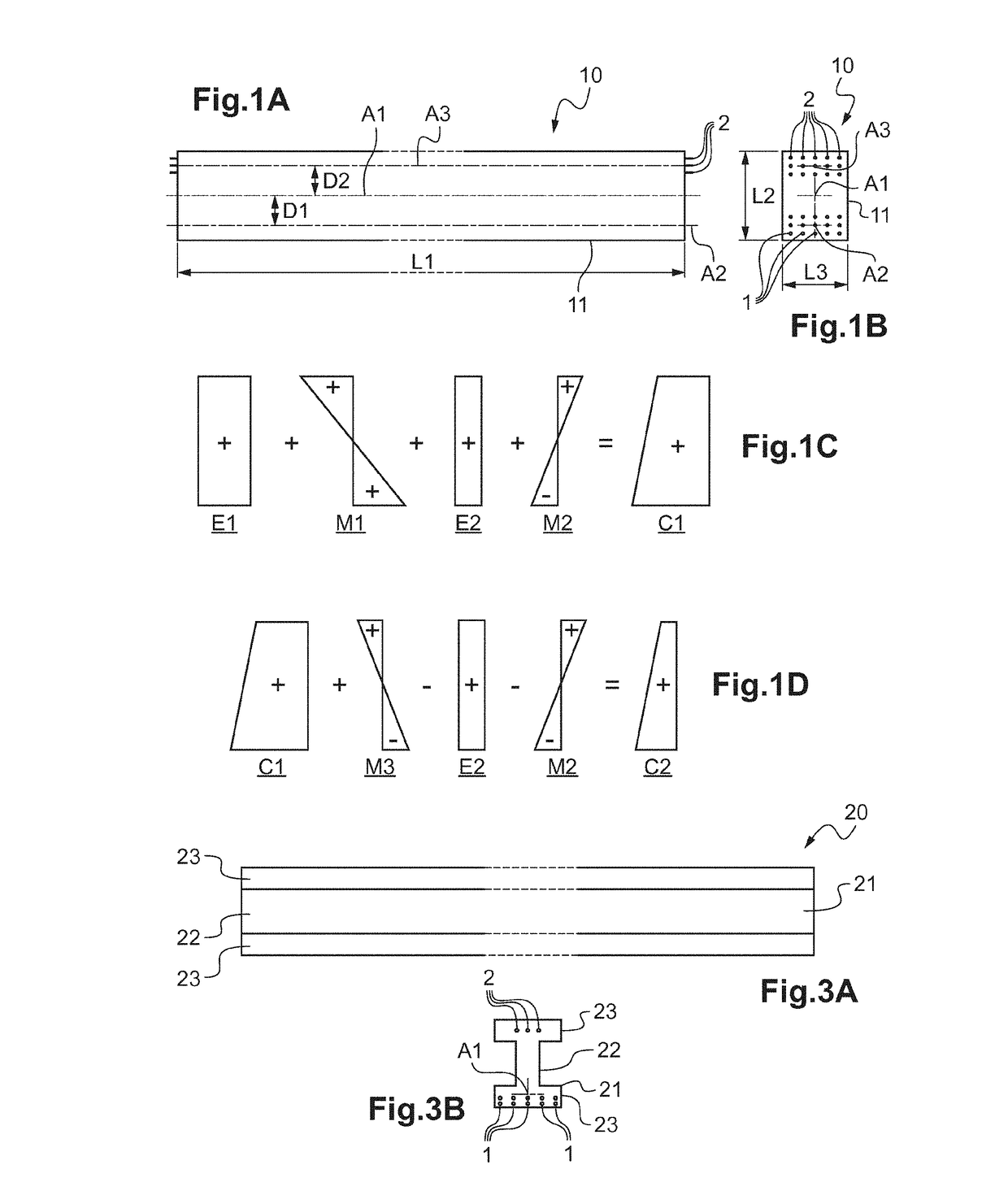
[0147]FIG. 3A shows a beam 20 of the invention.

[0148]In this embodiment, the body 21 of the beam 20 presents a cross-section that is I-shaped.

[0149]As shown in FIG. 3B, the body 21 of the beam 20 thus presents two parallel flanges 23 between which a vertical web 22 extends.

[0150]The first and second tensioners 1, 2 thus extend over the entire length of the beam 20, parallel to one another.

[0151]In this embodiment, five first tensioners 1 are provided, embedded in the concrete of the bottom flange 23 of the body 21 of the beam 20. In this embodiment, the first tensioners 1 are once more regularly distributed over the width of the beam 20. Thus, when they compress the body 21 of the beam 10, they do not deform it in twisting.

[0152]The five first tensioners 1 are situated in the proximity of the bottom face of the bottom flange 23. Thus, when they are tensioned, they make it possible to bend the body 21 of the beam 20 so that the center of the beam moves upwards.

[0153]Three second tens...

first embodiment

[0154]FIGS. 4A and 4B show a slab 30 of the invention.

[0155]In this embodiment, the body 31 of the slab 30 presents the general shape of a rectangular parallelepiped. Its neutral axis A1 thus coincides with the central longitudinal axis of the body 31.

[0156]In this embodiment, the ends of the slab 30 nevertheless present respective rims 32 projecting from the top face of the body 31. The two rims 32 run along the two ends of the body 31. They co-operate with each other to define a cavity 33 between them into which a screed could be poured.

[0157]The first and second tensioners 1, 2 extend over the entire length of the slab 30, parallel to one another.

[0158]In this embodiment, a plurality of first tensioners 1 are provided, embedded in the concrete of the body 31 of the slab 30. In this embodiment, the first tensioners 1 are once more regularly distributed over the width of the slab 30, below the neutral axis A1. They are situated in the proximity of the bottom face of the body 31 of ...


PUM


Abstract

The invention provides a prefabricated structural element including an elongate body (11) and at least one first tensioner (1) that is fastened in the elongate body in such a manner that it compresses the elongate body. The structural element includes at least one second tensioner (2) that is fastened to the elongate body at two distinct points by two fastener element so that it compresses the elongate body, at least one of the fastener element being removable so as to make it possible to relax the compression exerted on the elongate body by the second tensioner.

Description

TECHNICAL FIELD TO WHICH THE INVENTION RELATES[0001]The present invention generally relates to fabricating structural elements, in particular concrete beams, slabs, or blocks.[0002]It relates more particularly to a prefabricated structural element comprising an elongate body and at least one first tensioner that is fastened in the elongate body in such a manner that it compresses and bends the elongate body in a first direction.[0003]It also relates to a method of installing such a structural element in a work.[0004]The invention applies to any type of work, e.g. buildings, bridges, dams, . . . .TECHNOLOGICAL BACKGROUND[0005]During the building of such a work, it is common practice to use concrete beams and slabs.[0006]A well-known problem of concrete is that although it is good at withstanding compression forces, it cracks quickly when it is subjected to traction forces. Thus, it is estimated that concrete withstands compression forces twenty times better than traction forces.[0007...

Claims


Application Information

Patent Timeline
Patent Type & Authority Applications(United States)
IPC IPC(8): E04C3/20E04C5/16E04C5/01E04C5/12E04C3/02E04C3/26
CPCE04C3/20E04C3/02E04C5/162E04C5/01E04C5/12E04C3/26E04B5/043E04C5/10E04G21/12
Inventor SABBAH, ALAIN
Owner SABBAH ALAIN
Learn More