Evaluating Railway Ties

a technology for railway ties and crossties, applied in weather/light/corrosion resistance, instruments, material analysis, etc., can solve the problems of deteriorating concrete and wooden ties, railroads' problems, and the pattern of cracking along the sides of crossties and within crossties has advanced significantly, so as to improve signal quality, reduce noise, and reduce noise

Inactive Publication Date: 2017-08-03
VECTOR CORROSION SERVICES INC
View PDF11 Cites 19 Cited by
  • Summary
  • Abstract
  • Description
  • Claims
  • Application Information

AI Technical Summary

Benefits of technology

[0022]In the preferred arrangement the impact energy source comprises a body carried on a support which provides an impact on the surface of the tie and is immediately retracted so as to prevent sliding movement across the surface. In this way the source of energy is effectively instantaneous and there is no scraping of the body across the surface which can generate soundwaves (noise) which interferes with the analysis of the surface waves in the tie. It is important therefore to prevent extraneous sounds as much as possible so that the sensors also have no component contacting the surface of the tie which can generate extraneous noise in the surface waves. Yet further, additional steps can be taken to reduce extraneous vibrations / noise so as to avoid interfering with the sensor detection. For example the vehicle is preferably carried on wheels which are of a polymer, rubber or plastics material which is resilient or flexible to provide a quiet rolling action. Such wheels are also non-conductive and hence prevent grounding across the two rails which is unacceptable in railway management practice.
[0088]The system thus acts to work with the impact energy sources and shotgun microphone sensors. The system is light weight-entire with the system less than 150 pounds. The system uses quiet-polyurethane wheels, no sensor contact; automatic triggering using the proximity switch and rail clips; and tapper impact energy source so that there are no flying projectiles. The system can be portable so that it folds up for transport. There are no compressed gas bottles. The system carries the components for automatic data analysis and marking of the severely deteriorated crossties when detected. The use of polyurethane wheels is very quiet and reduces noise for the microphones.

Problems solved by technology

Concrete and wooden ties deteriorate in service.
It is well documented that deteriorating concrete and wooden ties are an issue for railroads.
Top cracks appear later-in-time and unfortunately are not an early indicator of deterioration.
Ties which have been removed from service demonstrate that by the time a crack is visible in the top surface to a length of several inches, the pattern of cracking along the sides of the crosstie and within the crosstie has progressed significantly.
Visual inspection of the exposed surfaces of ties is less capable of identifying ties in the early stages of cracking and deterioration compared to the non-destructive testing using an impact energy source.

Method used


Image

  • Evaluating Railway Ties
  • Evaluating Railway Ties
  • Evaluating Railway Ties

Examples


Embodiment Construction

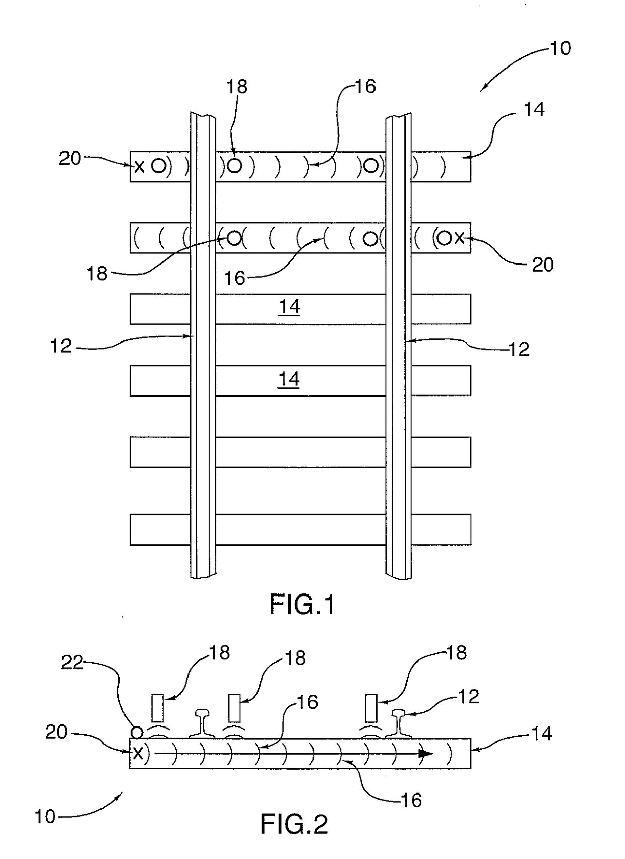
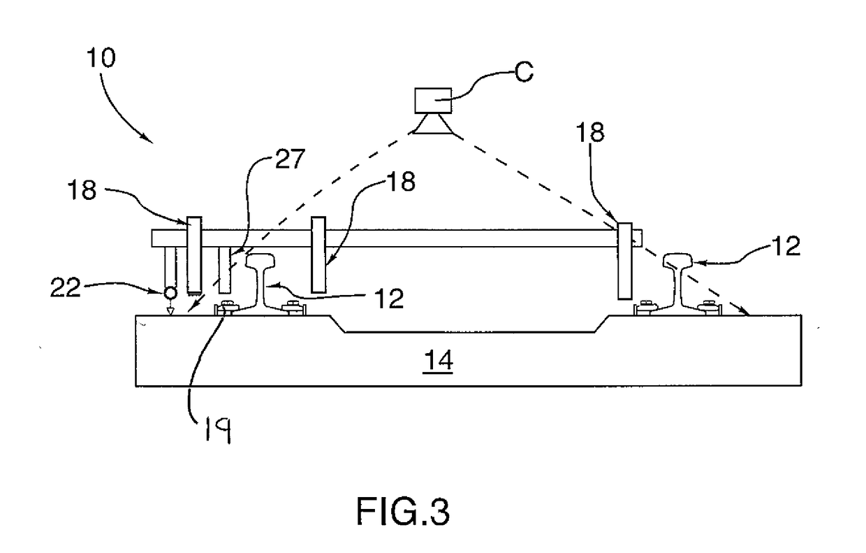
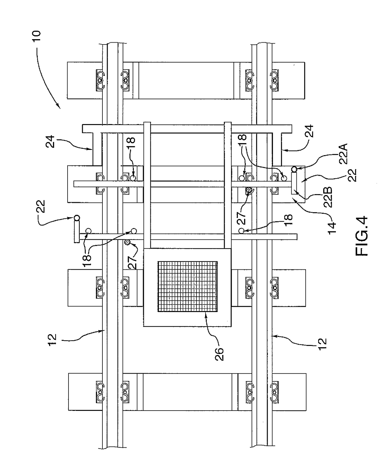
[0101]One example of a concrete testing system can be seen in the conceptual illustrations of FIGS. 1 (top view) and 2 (front view). In both figures a concrete testing system 10 may be moved upon railroad tracks 12 to evaluate the concrete railroad ties 14 to which they are secured. Waves which are typically Rayleigh but include compressional pressure waves 16 are propagated along and through the railroad tie 14. Sensing devices 18, such as microphones, detect the air pressure waves that emanate from the tie 14 due to movement of the surface of the ties due to the waves 16 within the structure.

[0102]The pressure waves 16 are generated at contact point 20 at one end of a concrete railroad tie 14 and propagate through the tie 14 from one end to the other. The sensing devices 18 are located along the length of the tie 14 to detect the pressure waves 16, allowing an assessment of the degree of cracking / concrete deterioration of the concrete tie 14.

[0103]FIG. 2 shows the location of the ...


PUM

PropertyMeasurementUnit
frequenciesaaaaaaaaaa

Abstract

A method of evaluating railway ties for deterioration is mounted on a moving vehicle along the rails where the presence of the tie is detected and an impact energy source is used to create at least one wave in a surface of the tie which travels longitudinally along the tie. At positions spaced longitudinally from the source, the time of arrival of the wave is detected typically by a series of sensors responsive to air pressure changes to determine a speed of propagation of the wave in the tie and, in the event that the speed in said tie is below a predetermined speed, an output indication is provided regarding the deterioration of the tie, which can include a real time marking of the tie detected.

Description

[0001]This application claims the benefit under 35 USC 119 (e) of Provisional Application 62 / 280,799 filed Jan. 20, 2016, the disclosure of which is incorporated herein by reference.[0002]This invention relates to a method of evaluating railway ties for deterioration. The method can be carried out by passing the system over a plurality of ties carrying rails so as to generate data on each of the ties. This method can be used to determine the need to replace specific individual highly deteriorated ties or can be used to develop a maintenance program for replacing all ties in a particular area. In this way the safety of a rail system can be better maintained with potential for lower cost of replacement of the ties.BACKGROUND OF THE INVENTION[0003]Wood ties are widely used in rail systems. Concrete ties are a key element in high speed rail. Concrete and wooden ties deteriorate in service. A reliable scientific assessment of the structural performance of each tie is essential to ensure ...

Claims


Application Information

Patent Timeline
Patent Type & Authority Applications(United States)
IPC IPC(8): G01N3/30G01N17/00
CPCG01N17/006G01N3/30G01N29/045G01N2291/106G01N2291/2623
Inventor FISK, PAULDE RIVERA, ERICARMITAGE, BENSON
Owner VECTOR CORROSION SERVICES INC
Why Eureka
Try Eureka