Hierarchical time stamping

a time stamping and hierarchy technology, applied in the field of data networking, can solve the problems of increasing the cost of implementation, increasing the latency of network data propagation through the network nodes,

Active Publication Date: 2017-08-03
ARISTA NETWORKS
View PDF47 Cites 13 Cited by
  • Summary
  • Abstract
  • Description
  • Claims
  • Application Information

AI Technical Summary

Problems solved by technology

When the amount of network data that is to be transmitted by one of the ports on a network element, or the overall data transmitted by a network element, is greater than the port or network element can handle within a given period, network congestion can occur, resulting in increased latency for network data propagation through the nodes on the network.
One challenge presented by the use of such tools is that any time stamping or latency analysis is performed on only a subset of the network.
A second timing network may be used to gain detailed analysis of network performance, but at a greatly increased cost of implementation.

Method used


Image

  • Hierarchical time stamping
  • Hierarchical time stamping
  • Hierarchical time stamping

Examples


Embodiment Construction

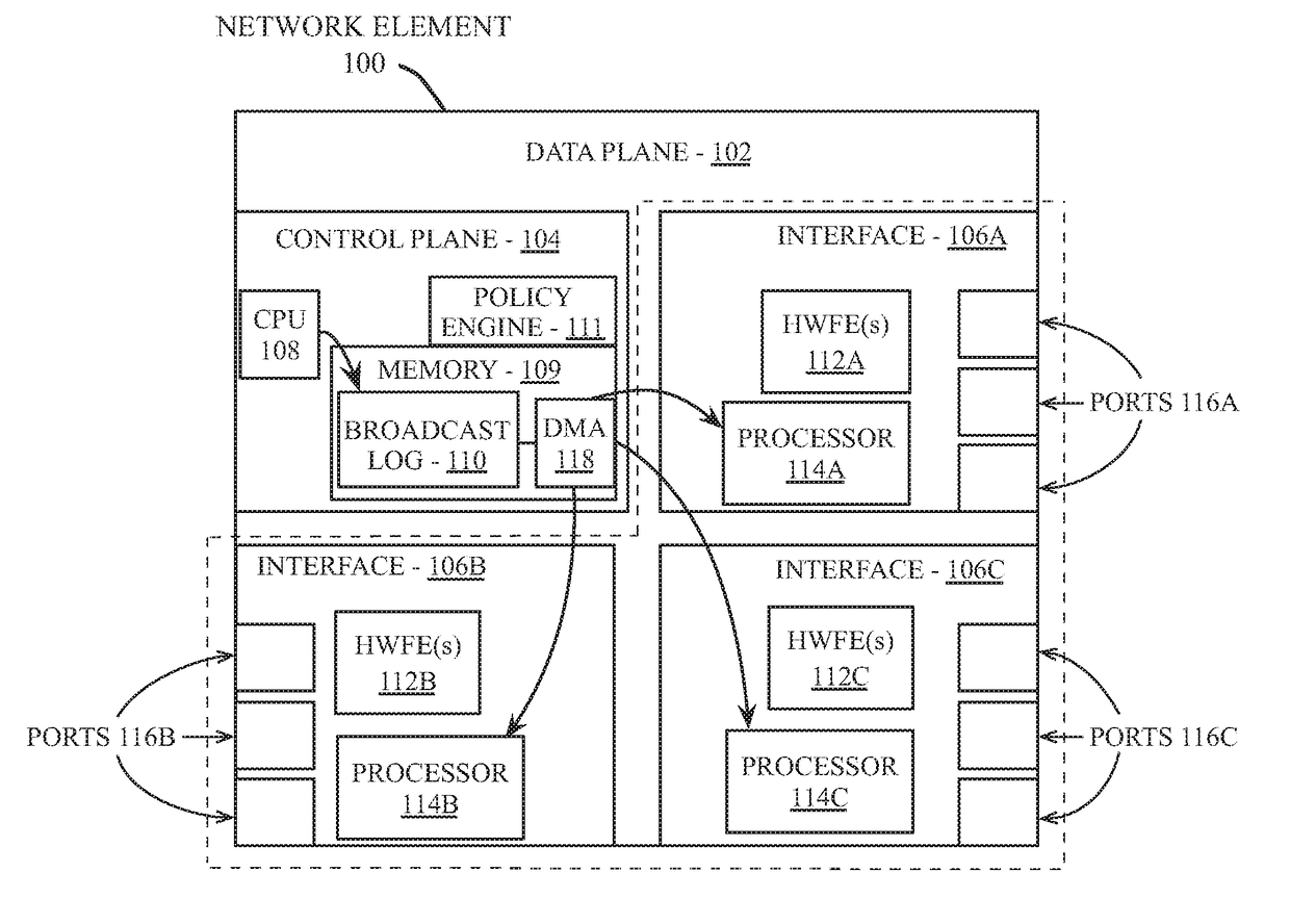
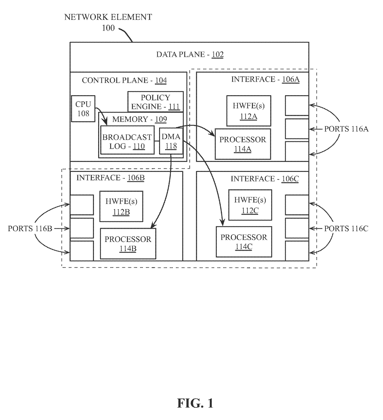
[0023]Embodiment described herein can be implemented in a network including enterprise level network elements (e.g., switch, router, etc.) having hardware assisted time stamping for production network data. One embodiment provides a hierarchical time stamping system in which time stamps are applied to network data as the data arrives at each node on the network. The time stamps are applied hierarchically, where an additional time stamp is appended to each unit of network data at each node within the network. The time stamps can be used to determine node-to-node latency within the network for production traffic, as well as determine the path of each unit of network data (e.g., packet, datagram, frame, etc.) as the data traverses the network.

[0024]To provide a thorough explanation of the various embodiments, numerous specific details are set forth herein. However, one having ordinary skill in the art will understand that embodiments may be practiced without these specific details. In ...


PUM


Abstract

Various embodiments are described herein, which provide a network element comprising a network port to receive production network data that is used for purposes other than testing the performance of a network, a data plane coupled to the network port, the data plane including a timing module to append a time stamp to a set of one or more time stamps included within the production network data, and a control plane coupled to the data plane, the control plane including a latency analyzer to analyze the set of one or more time stamps included within the production network data.

Description

FIELD OF INVENTION[0001]This invention relates generally to data networking and more particularly to network latency analysis.BACKGROUND OF THE INVENTION[0002]A network element (such as a router or switch) transmits and receives network data using one or more ports of that network element. Each port on the network element has a physical link speed that limits the rate at which network data can be transmitted from that port. The network element uses one or more queues to store the network data that is to be transmitted from one of the ports of the network element. The maximum data that a queue stores is determined by the available buffer memory and a buffer configuration for the queue. When the amount of network data that is to be transmitted by one of the ports on a network element, or the overall data transmitted by a network element, is greater than the port or network element can handle within a given period, network congestion can occur, resulting in increased latency for networ...

Claims


Application Information

Patent Timeline
Patent Type & Authority Applications(United States)
IPC IPC(8): H04L12/26H04L12/715
CPCH04L45/04H04L43/106H04L43/0858H04L43/0852
Inventor SADANA, ANSHULPARTHASARATHY, PRASANNASWEENEY, ADAM JAMES
Owner ARISTA NETWORKS
Why Eureka
Try Eureka