

Bearing structure for vehicle pedal device and flanged bushing
- Summary
- Abstract
- Description
- Claims
- Application Information
AI Technical Summary
Benefits of technology
Problems solved by technology
Method used
Image

Examples
embodiment
[0031]An embodiment of the present invention will be described in detail below with reference to the accompanying drawings. In the following embodiment, the drawings other than FIGS. 4 and 5 are shown simplified or deformed as appropriate for explanation purposes, and the proportions, shapes, etc. of the parts are not necessarily accurately shown in the drawings. The proportions and shapes shown in FIGS. 4 and 5 are close to the actual proportions and shapes in order to facilitate understanding.
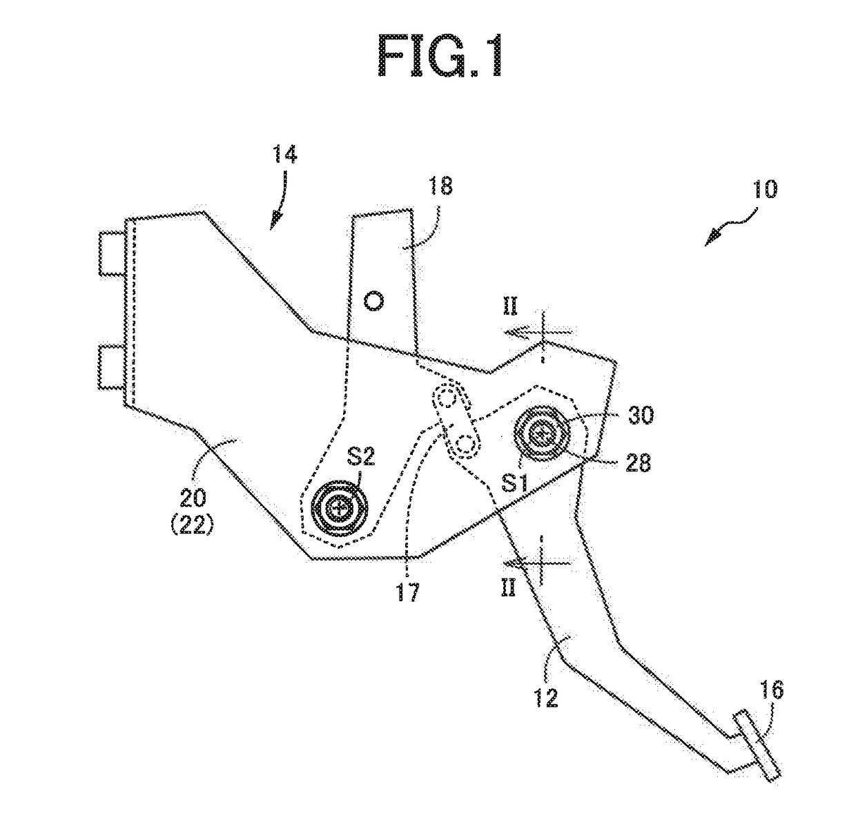
[0032]FIG. 1 is a left side view showing a brake pedal device 10 for service brakes of vehicles to which the present invention is applied, and FIG. 2 is an enlarged sectional view taken along line II-II and viewed in the direction II in FIG. 1. The brake pedal device 10 includes a brake pedal 12. The brake pedal 12 is supported at its upper end by a pedal bracket 14 such that the brake pedal 12 can pivot about a support axis 51, which is substantially horizontal. A stepping portion 16 such as...
PUM
 Abstract
Description
Claims
Application Information