Torque transmission joint and electric power steering device

Active Publication Date: 2019-07-11
NSK LTD
View PDF0 Cites 6 Cited by
  • Summary
  • Abstract
  • Description
  • Claims
  • Application Information

AI Technical Summary

Benefits of technology

[0035]According to the above-described torque transmission joint and electric power steering device, generation of an abnormal noise can be suppressed when reversing a rotational direction of a driving shaft.
[0036]That is, in the above configuration, the driving-side concave-convex portion is engaged with the one axial end portion of the intermediate concave-convex portion with a circumferential gap being interposed therebetween, and the driven-side concave-convex portion is engaged with the another axial end portion of the intermediate concave-convex portion with a circumferential gap being interposed therebetween. Therefore, when torque is transmitted from the driving shaft to the driven shaft, in an initial stage, in engagement portions between the elastic member and the driving-side concave-convex portion and the driven-side concave-convex portion, the circumferential side surfaces of the convex portions configuring the driving-side concave-convex portion and the driven-side concave-convex portion can come into contact with the circumferential side surface of the convex portions configuring the intermediate concave-convex portion after the elastic deformation of the elastic mem

Problems solved by technology

However, it is not possible to suppress an abnormal noise, which is to be generated at a coupling portion between a tip portion of an output shaft 12 of

Method used


Image

  • Torque transmission joint and electric power steering device
  • Torque transmission joint and electric power steering device
  • Torque transmission joint and electric power steering device

Examples


Example

[0058]A first embodiment of the present invention will be described with reference to FIGS. 1 to 17.

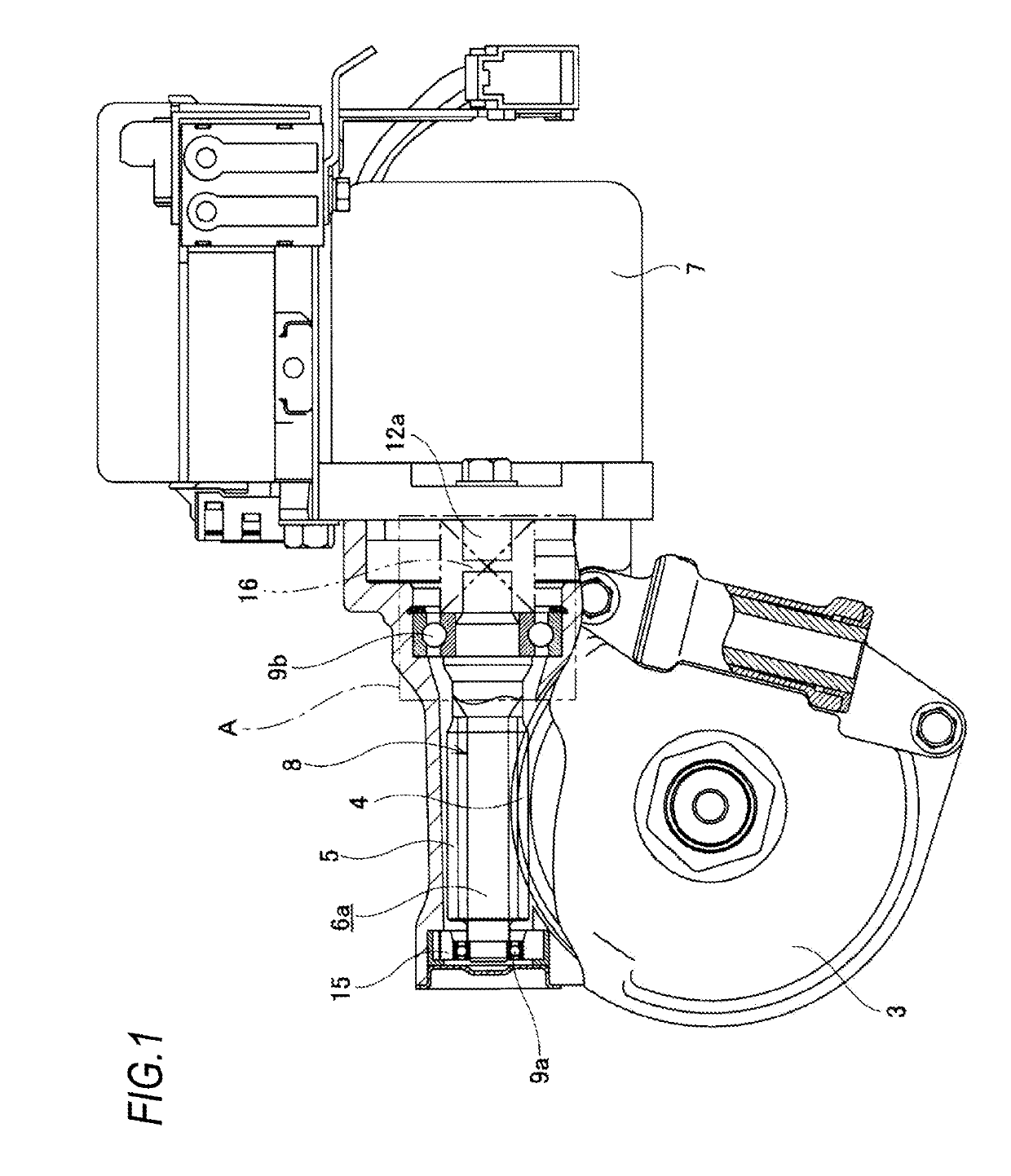
[0059]In an electric power steering device of the first embodiment, a front end portion of a steering shaft 2 to which a steering wheel 1 is attached at a rear end portion is rotatably supported in a housing 3, and a worm wheel 4 is fixed to a portion configured to rotate by the steering shaft 2, similarly to the conventional structure shown in FIGS. 18 and 19. Worm teeth 5 configured to mesh with the worm wheel 4 are provided on an axially intermediate portion of a worm shaft 6a, and both axial end portions of a worm 8 configured to rotate by an electric motor 7 are rotatably supported in the housing 3 by a pair of rolling bearings (ball bearings in the illustrated example) 9a, 9b. A preload applying mechanism 15 including an elastic body such as a coil spring or a leaf spring is provided between the housing 3 and the rolling bearing 9a externally fitted to a tip portion of the worm ...

Example

[0128]A second embodiment of the present invention will be described with reference to FIG. 20.

[0129]As shown in FIG. 20, a torque transmission joint of the second embodiment is provided with a ring-shaped (with equal cutouts in a circumferential direction) stopper protrusion 70 at a center portion in a width direction of an inner periphery of an intermediate transmission member 19a. In the first embodiment described above, when the torque transmission joint is in an assembled state, a space between an end surface of a driving-side transmission member 17a which is on an opposite side to a collar portion 25 and an end surface of a driven-side transmission member 18a which is on an opposite side to a collar portion 29 is larger than a space between an end surface of a periphery covering piece 40a of a driving-side elastic member 20 and an end surface of a periphery covering piece 40b of a driven-side elastic member 21. In contrast, the two spaces are set to the same size in the second...


PUM


Abstract

A driving-side concave-convex portion of a driving-side transmission member is engaged with an elastic member. The driving-side concave-convex portion is engaged with an intermediate concave-convex portion of an intermediate transmission member with a circumferential gap being interposed therebetween. A driven-side concave-convex portion of a driven-side transmission member is engaged with the elastic member. The driven-side concave-convex portion is engaged with the intermediate concave-convex portion with a circumferential gap being interposed therebetween. Both axial side surfaces and a periphery of the intermediate transmission member are covered by a side surface covering portion and a periphery covering portion of the elastic member.

Description

TECHNICAL FIELD[0001]The present invention relates to a torque transmission joint which is to be incorporated into various mechanical devices and used for transmission of torque between a driving shaft and a driven shaft. The present invention also relates to an electric power steering device which is to be used as a steering device of an automobile and is configured to use an electric motor as an auxiliary power source, thereby reducing a force necessary for a driver to operate a steering wheel.BACKGROUND ART[0002]FIGS. 18 and 19 show an example of a known electric power steering device described in Patent Document 1.[0003]A front end portion of a steering shaft 2 to which a steering wheel 1 is attached at a rear end portion is rotatably supported in a housing 3, and a worm wheel 4 is fixed to a portion configured to rotate by the steering shaft 2. Worm teeth 5 configured to mesh with the worm wheel 4 are provided on an axially intermediate portion of a worm shaft 6, and both axial...

Claims


Application Information

Patent Timeline
IPC IPC(8): F16D3/74F16H1/16B62D5/04
CPCF16D3/74F16H1/16B62D5/0409B62D5/0403F16H55/24F16D3/68F16D3/54
Inventor ISHII, TORUSEGAWA, TORUOOSAWA, RYOUNISHIMURA, NOBUYUKI
Owner NSK LTD
Why Eureka
Try Eureka