

Seat belt device
Patent Information
- Authority / Receiving Office
- US · United States
- Current Assignee / Owner
- HONDA MOTOR CO LTD
- Publication Date
- 2014-05-01
Smart Images
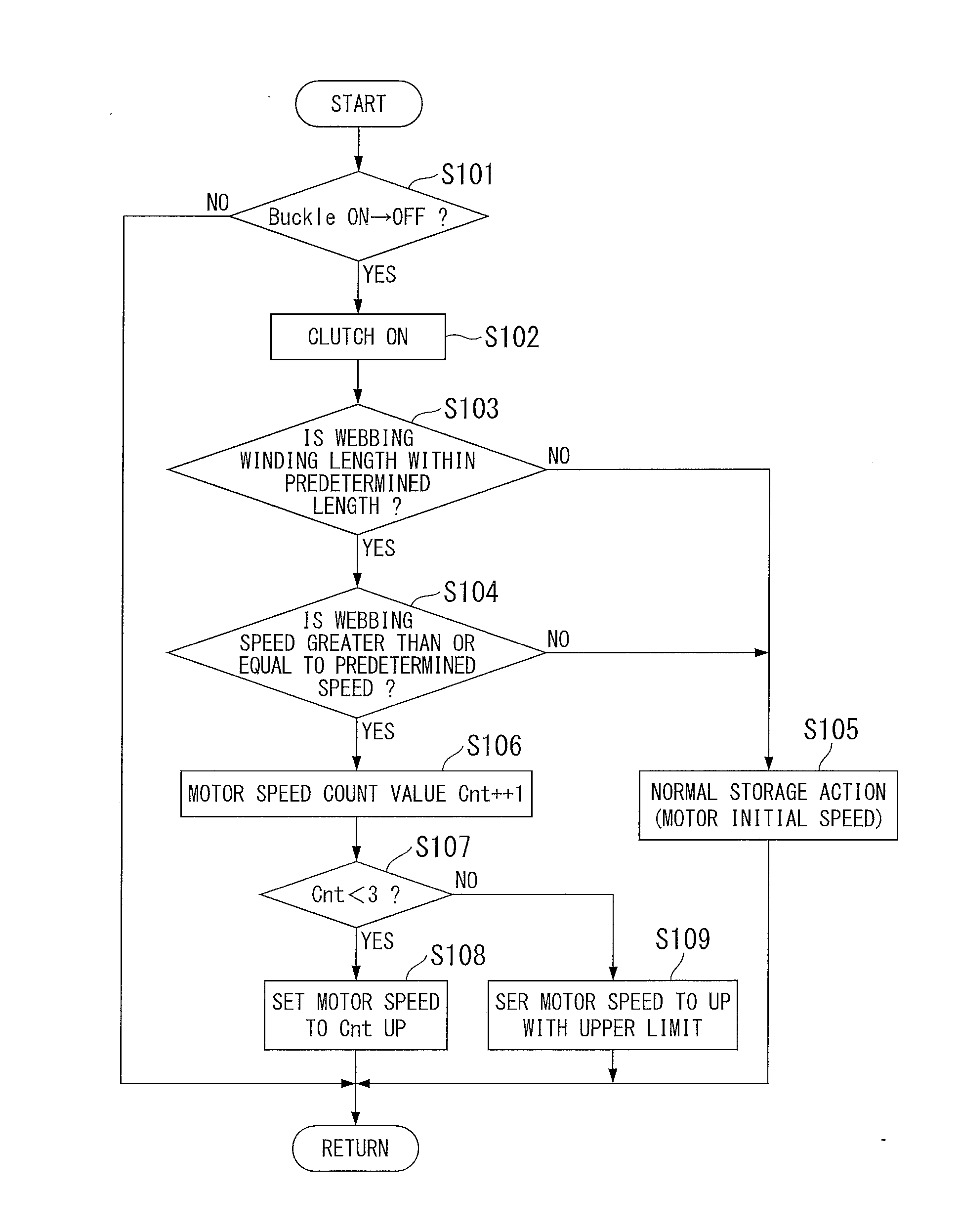
Figure 1 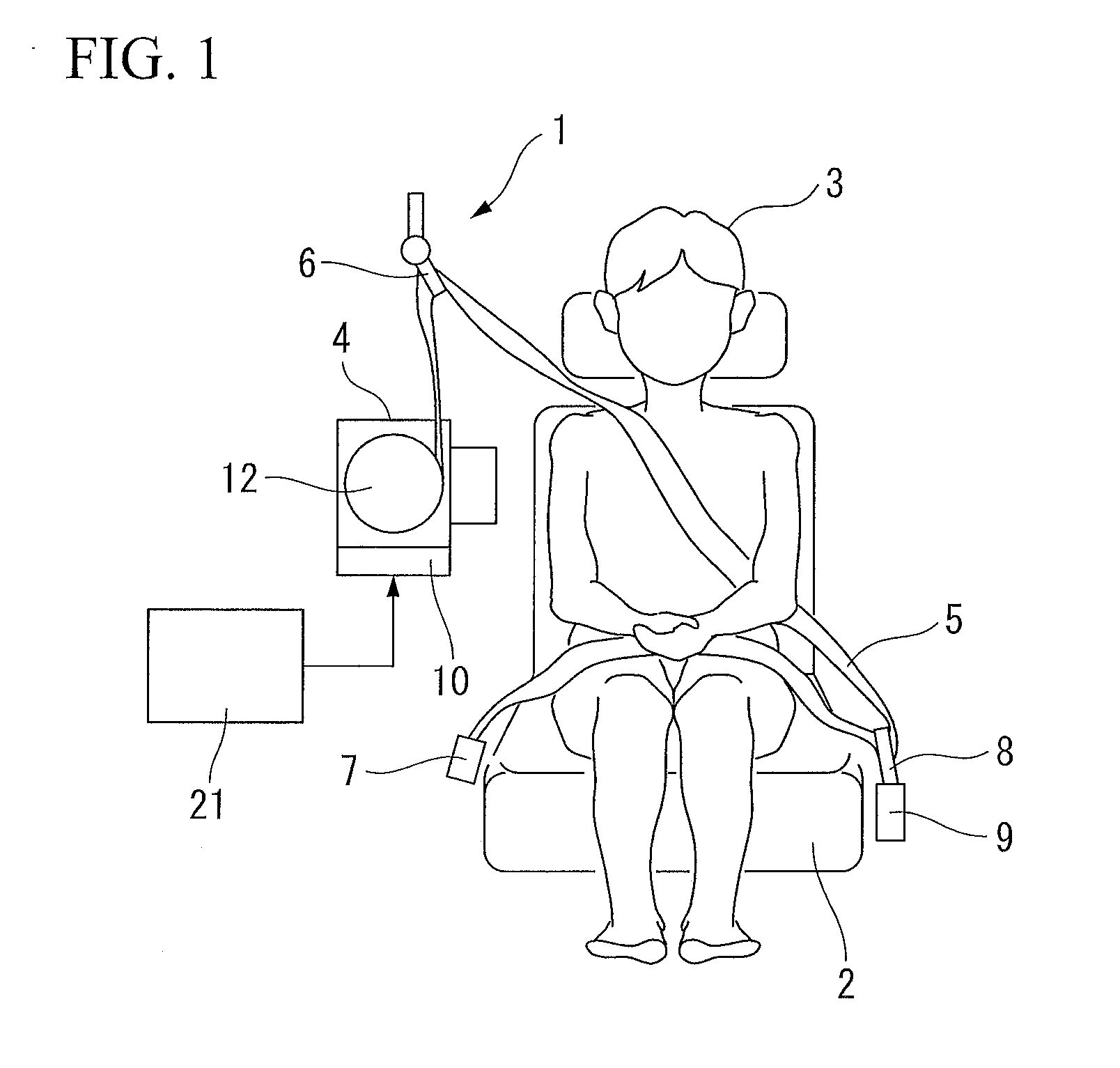
Figure 2 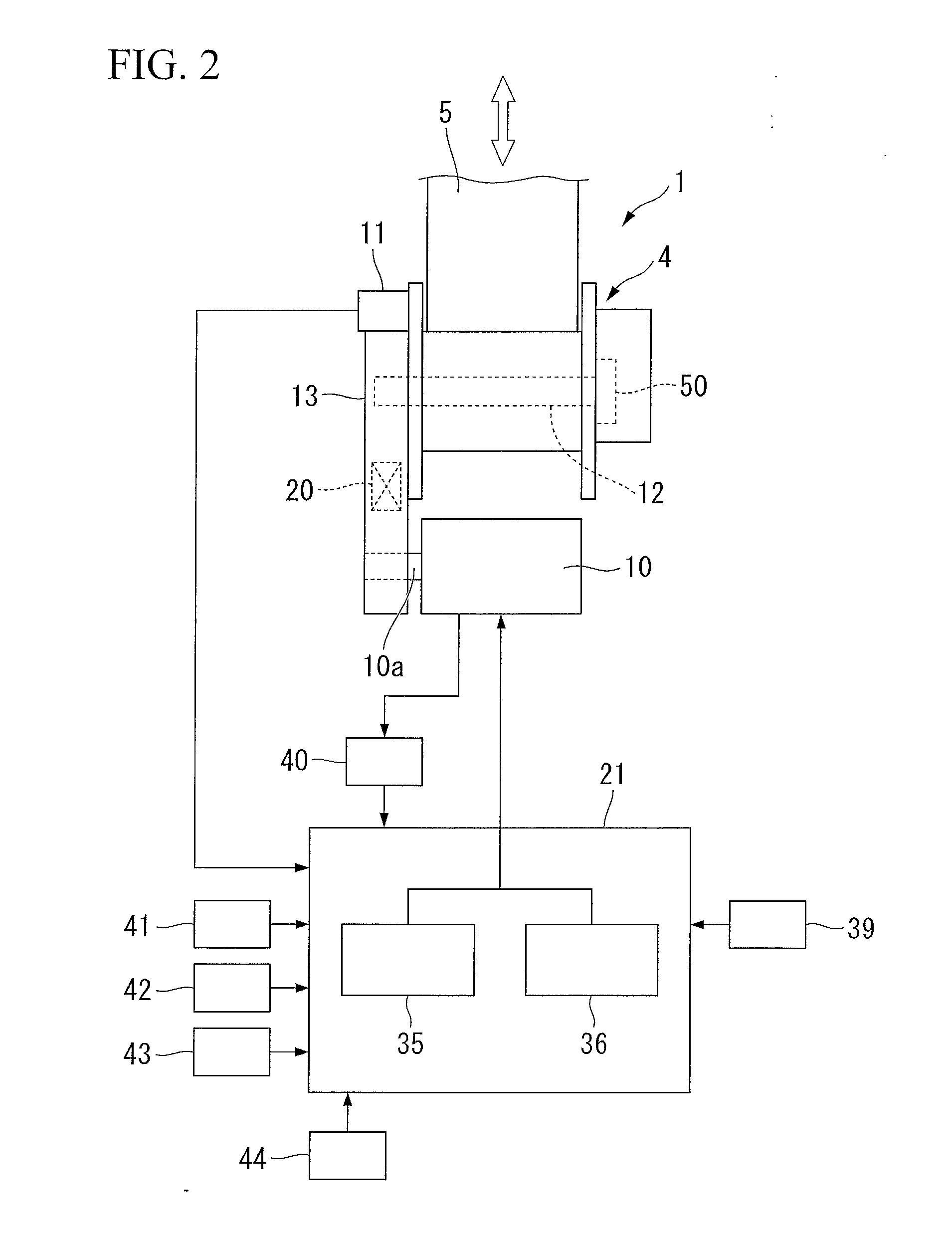
Figure 3
Abstract
Description
TECHNICAL FIELD
[0001] The present invention relates to a seat belt device that restrains a passenger who sits in a seat of a vehicle using webbing. Priority is claimed on Japanese Patent Application No. 2011-182524, filed Aug. 24, 2011, the content of which is incorporated herein by reference.BACKGROUND ART
[0002] In seat belt devices that are equipped in vehicles, webbing for restraining passengers is wound around a belt reel and the belt reel is accommodated within a retractor in a state of being biased in a webbing winding direction (there are cases below in which this is simply referred to as a winding direction) by a winding spring. Therefore, when the webbing is fastened, the webbing is drawn out against the biasing force of the winding spring, and when the webbing is released, the webbing is wound onto the belt reel by the biasing force of the winding spring.
[0003] In recent years, seat belt devices which are provided with a motor for drawing the webbing in have been developed. I...