Hydraulic Manifold Control Assembly

a manifold control and hydraulic technology, applied in the direction of sealing/packing, servomotor components, borehole/well accessories, etc., can solve the problems of increasing the cost of installing a given bop and diverter control system, and -based control systems further increasing the cost and complexity of conventional systems

Active Publication Date: 2017-08-17
STELLA MARIS LLC
View PDF6 Cites 15 Cited by
  • Summary
  • Abstract
  • Description
  • Claims
  • Application Information

AI Technical Summary

Problems solved by technology

All of these specialized piping and tubing runs can significantly increase the cost of installing a given BOP and diverter control system.
This air-based control system further increases the cost and complexity of conventional systems.
This hardened equipment again increases the cost, and bulk, of conventional systems.

Method used


Image

  • Hydraulic Manifold Control Assembly
  • Hydraulic Manifold Control Assembly
  • Hydraulic Manifold Control Assembly

Examples


Embodiment Construction

[0038]The word “exemplary” is used herein to mean “serving as an example, instance, or illustration.” Any configuration or design described herein as “exemplary” is not necessarily to be construed as preferred or advantageous over other configurations or designs.

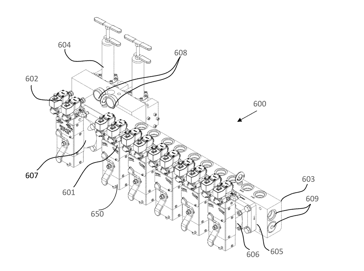
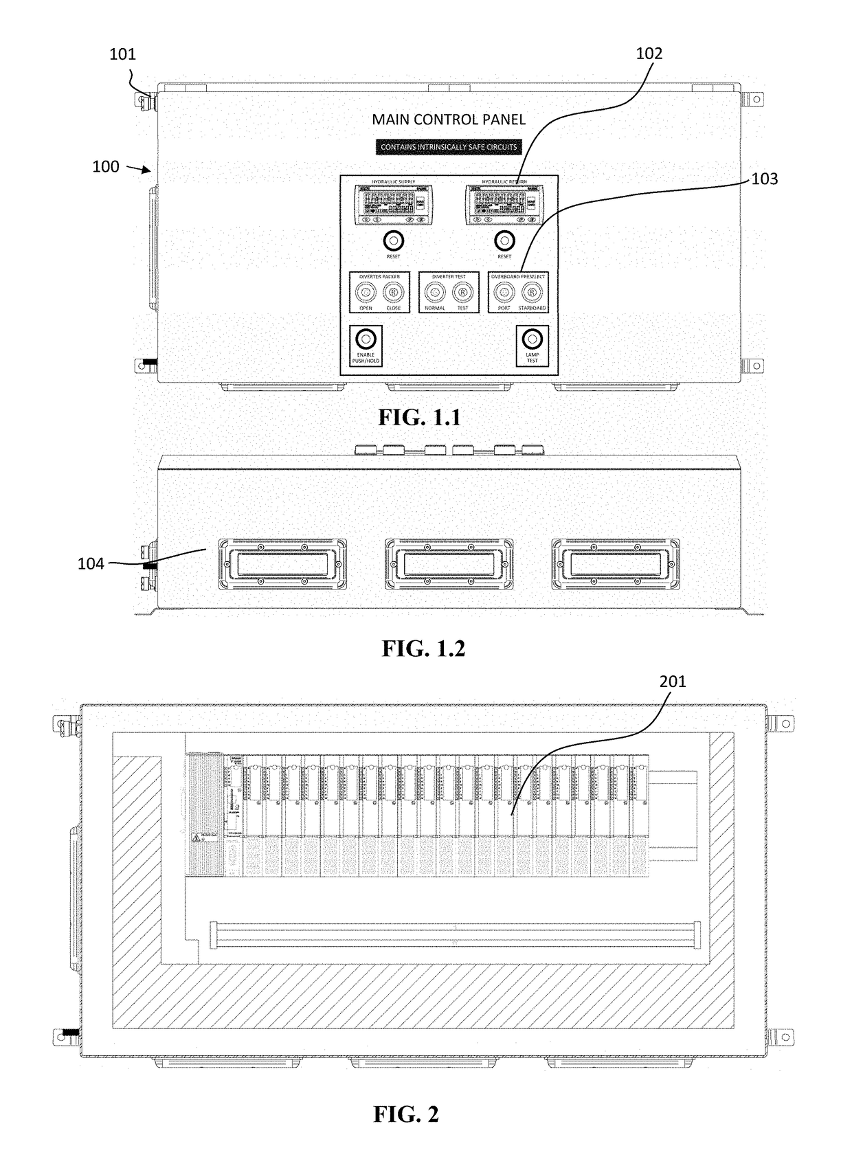
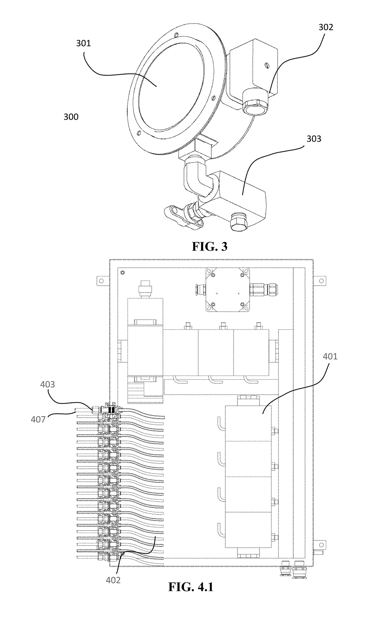
[0039]The invention focuses on different unique design elements and employment methods incorporated within the surface blowout preventer (BOP) and diverter control system design (also referred to herein as the Hydraulic Manifold Control Assembly). These design elements and methods contribute to an improved design by reducing overall envelope dimensions, improving maintenance accessibility, and reducing overall installation and manufacturing time, and ultimately contributing to a more robust, cost effective end-product. The design elements and methods implemented for an improved design include: the use of intrinsically safe I / O modules and components; the employment of a removable valve assembly rack installation method; the ...


PUM


Abstract

A Hydraulic Manifold Control Assembly for use in connection with surface blowout preventers and diverter control systems. Said Hydraulic Manifold Control Assembly incorporates design elements and methods which reduce overall envelope dimensions, improving maintenance accessibility, thereby reducing overall installation and manufacturing time and ultimately contributing to a more robust, cost effective end-product. Said design elements and methods include: the use of intrinsically safe I / O modules and components; the employment of a removable valve assembly rack installation method; the use of a removable face plate for identification of flow control valves; the implementation of a digital automatic diverter sequence; the use of integrated manifold assemblies; and the integration of a wide-range function count.

Description

CROSS-REFERENCE TO RELATED APPLICATIONS[0001]The present application claims priority from U.S. Provisional Application No. 62 / 253,518, filed Nov. 10, 2015, which is incorporated herein by reference as if set forth in full below.BACKGROUND OF THE INVENTION[0002]I. Field[0003]The invention relates to a control system designed for the operation of surface blowout preventer (BOP) and diverter systems. More specifically, the unique design elements and employment methods incorporated within the control system that offer an improvement over conventional methods and designs.[0004]II. Background[0005]Blowout preventers (BOP) and diverter control systems incorporate the use of flow control and electrical components to deliver hydraulic fluid to rams, valves, seals, and other types of equipment for their operation. These systems also provide means of monitoring key factors measured during well control operations.[0006]The systems feature two different modes of operation: local manual and remot...

Claims


Application Information

Patent Timeline
Patent Type & Authority Applications(United States)
IPC IPC(8): F15B13/02E21B33/06F15B21/02
CPCF15B13/022E21B33/063F15B21/02E21B34/16F15B13/081F15B13/0814F15B13/0825F15B13/0896F15B2013/006
Inventor LEBLANC, RYAN A.STUTES, PAUL W.GARY, RYAN S.MENARD, MICHAEL P.DENISON, JACOB R.CHINCHILLA, LUIS A.WILLIAMSON, CALVIN R.CHANDRA MALLAVALLI, DEVI SATISHDUGAS, RYAN J.RAY, JAMES G.HULSEY, CLAY S.
Owner STELLA MARIS LLC
Why Eureka
Try Eureka