System and method for detecting defects on a specular surface with a vision system

a technology a specular surface, applied in the field of machine vision systems, can solve problems such as limitations in setup and use, defects and surface imperfections, and prove the challenge of a vision system, and achieve the effect of suppressing scattered light and enhancing or suppressing scattered ligh

Active Publication Date: 2017-08-17
COGNEX CORP
View PDF8 Cites 9 Cited by
  • Summary
  • Abstract
  • Description
  • Claims
  • Application Information

AI Technical Summary

Problems solved by technology

Performing surface inspection on objects with a specular surface finish can prove challenging for a vision system.
In general, reflections from the surface can cause defects and surface imperfections (e.g. small craters / valleys and / or bumps / hills), which represent a small difference in slope over a small area relative to the surrounding surface, to appear washed out by the large volume of reflected light entering the camera.
However, this technique has limitations in terms of setup and use in e.g. an environment that includes relative motion between the object and the camera assembly.

Method used


Image

  • System and method for detecting defects on a specular surface with a vision system
  • System and method for detecting defects on a specular surface with a vision system
  • System and method for detecting defects on a specular surface with a vision system

Examples


Embodiment Construction

[0030]I. System Overview

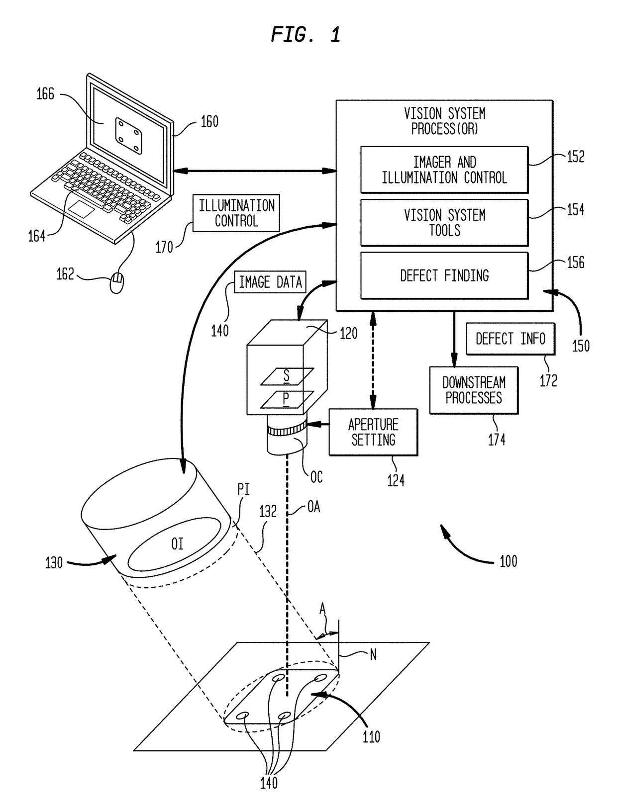
[0031]FIG. 1 is a diagram of an exemplary vision system arrangement 100 according to an illustrative embodiment in which the scene contains a stationary, specular object 110 located with respect to a stationary vision system camera 120. In this embodiment, the vision system camera 120 includes a two-dimensional (2D) image sensor S comprising an N×M array of pixels in an (e.g.) rectangular arrangement. The camera includes an optics package OC that can comprise any acceptable lens assembly (e.g. a lens with a C-mount, F-mount or M12 base). In this embodiment, the lens includes a manual or automated aperture control—for example a variable iris—in which the user or another external controller can input an appropriate aperture setting 124 (as described further below). The sensor S and optics OC collectively define an optical axis OA that is generally normal to the generalized surface plane of the object 110. The arrangement 100 includes an illuminator, 130 that pr...


PUM

PropertyMeasurementUnit
diameteraaaaaaaaaa
diameteraaaaaaaaaa
diameteraaaaaaaaaa

Abstract

This invention provides a system and method for detecting and imaging specular surface defects on a specular surface that employs a knife-edge technique in which the camera aperture or an external device is set to form a physical knife-edge structure within the optical path that effectively blocks reflected rays from an illuminated specular surface of a predetermined degree of slope values and allows rays deflected at differing slopes to reach the vision system camera sensor. The light reflected from the flat part of the surface is mostly blocked by the knife-edge. Light reflecting from the sloped parts of the defects is mostly reflected into the entrance aperture. The illumination beam is angled with respect to the optical axis of the camera to provide the appropriate degree of incident angle with respect to the surface under inspection. The surface can be stationary or in relative motion with respect to the camera.

Description

RELATED APPLICATION[0001]This application claims the benefit of co-pending U.S. Provisional Application, Ser. No. 62 / 255,360, entitled SYSTEM AND METHOD FOR DETECTING DEFECTS ON A SPECULAR SURFACE WITH A VISION SYSTEM, filed Nov. 13, 2015, U.S. Provisional Application, Ser. No. 62 / 274,094, entitled SYSTEM AND METHOD FOR DETECTING DEFECTS ON A SPECULAR SURFACE WITH A VISION SYSTEM, filed Dec. 31, 2015, and U.S. Provisional Application, Ser. No. 62 / 404,431, entitled SYSTEM AND METHOD FOR DETECTING DEFECTS ON A SPECULAR SURFACE WITH A VISION SYSTEM, filed Oct. 5, 2016, the teachings of each of which applications is expressly incorporated herein by reference.FIELD OF THE INVENTION[0002]This invention relates to machine vision systems for inspecting surfaces of objects and more particularly to vision systems that inspect specular surfaces.BACKGROUND OF THE INVENTION[0003]Machine vision systems, also termed “vision systems” herein, are used to perform a variety of tasks in a manufacturing...

Claims


Application Information

Patent Timeline
Patent Type & Authority Applications(United States)
IPC IPC(8): G06T7/00G02B5/00G02B27/28G01N21/95G02B27/10G02B3/06G01N21/88H04N5/225G02B5/30
CPCG06T7/0004H04N5/2256G02B5/005G02B27/286G02B5/3083G01N2021/9513G02B3/06G01N21/8806G01N21/95G06T2207/30148G01N2021/8848G02B27/10H04N23/56
Inventor ROSTAMI, FARIBORZFILHABER, JOHN F.QIAN, FENG
Owner COGNEX CORP
Why Eureka
Try Eureka