
Continuous-flow extraction system and method

a technology of continuous flow and extraction system, which is applied in the direction of fatty oil/fat production, separation process, fatty substance production, etc., can solve the problems of not providing for continuous regeneration of the properties of used hydrocarbon solvent, and the heating jacket of this publication does not supply heat and cold to the interior of the separator vessel

Active Publication Date: 2017-08-24
ELLIS MATTHEW
View PDF1 Cites 13 Cited by
  • Summary
  • Abstract
  • Description
  • Claims
  • Application Information

AI Technical Summary

Benefits of technology

This invention provides a system and method for extracting oil from plant parts or biomass using a continuous process with multiple extraction vessels. The system includes a de-waxer, primary and secondary jacketed separator vessels for purifying and refining the solvent, and heating, cooling, and pumping equipment necessary for the process. The technical effects include improved efficiency and productivity, as well as reduced solvent consumption and environmental impact.

Problems solved by technology

Additionally, present systems and methods do not provide for continuous regeneration of the used hydrocarbon solvent's properties, such that a smaller total amount of solvent can be used in an essentially closed, continuous loop.
However, the heating jacket of this publication does not supply heat and cold to the interior of the separator vessel and the expansion filter and help evaporate and condense the solvent.
However, this design provides for the use of filter only at the bottom of the extraction zone.

Method used


Image

  • Continuous-flow extraction system and method
  • Continuous-flow extraction system and method
  • Continuous-flow extraction system and method

Examples


Embodiment Construction

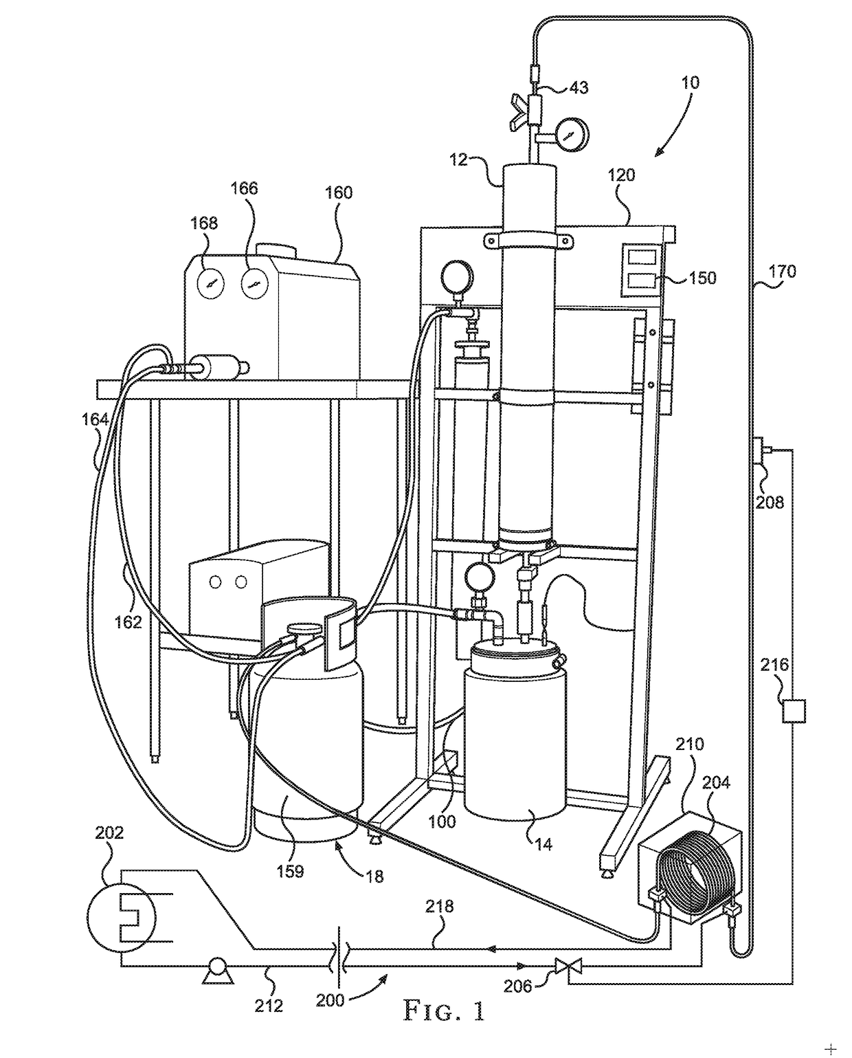
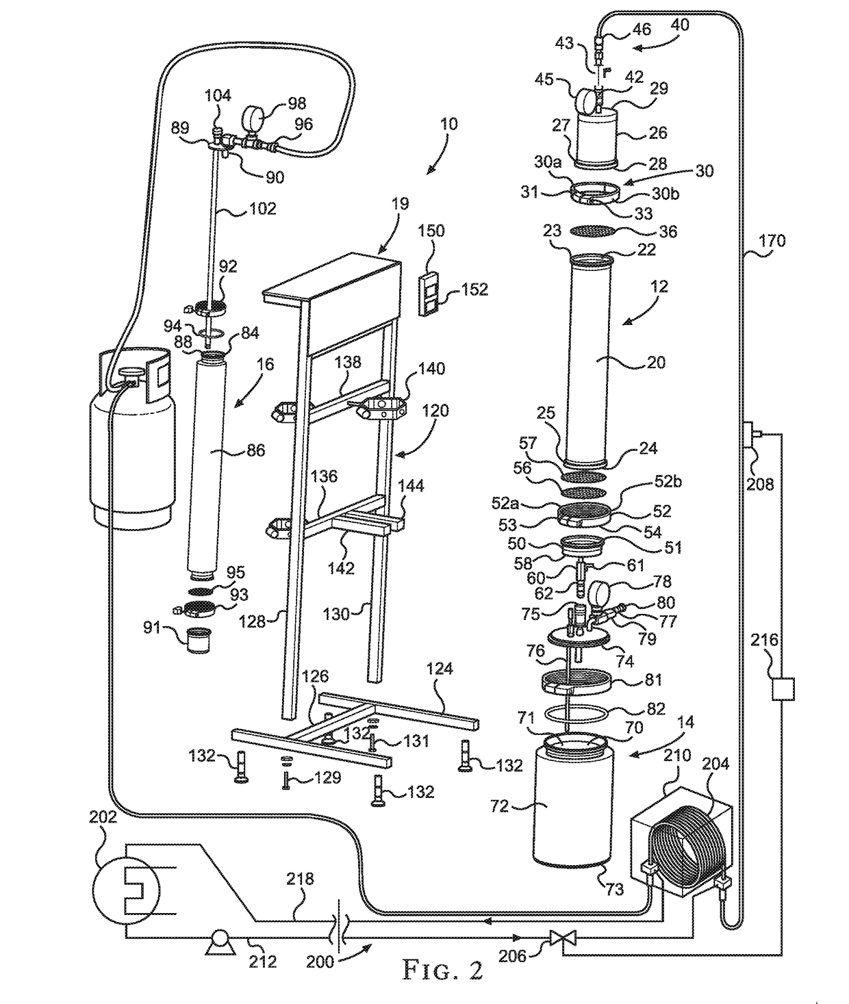
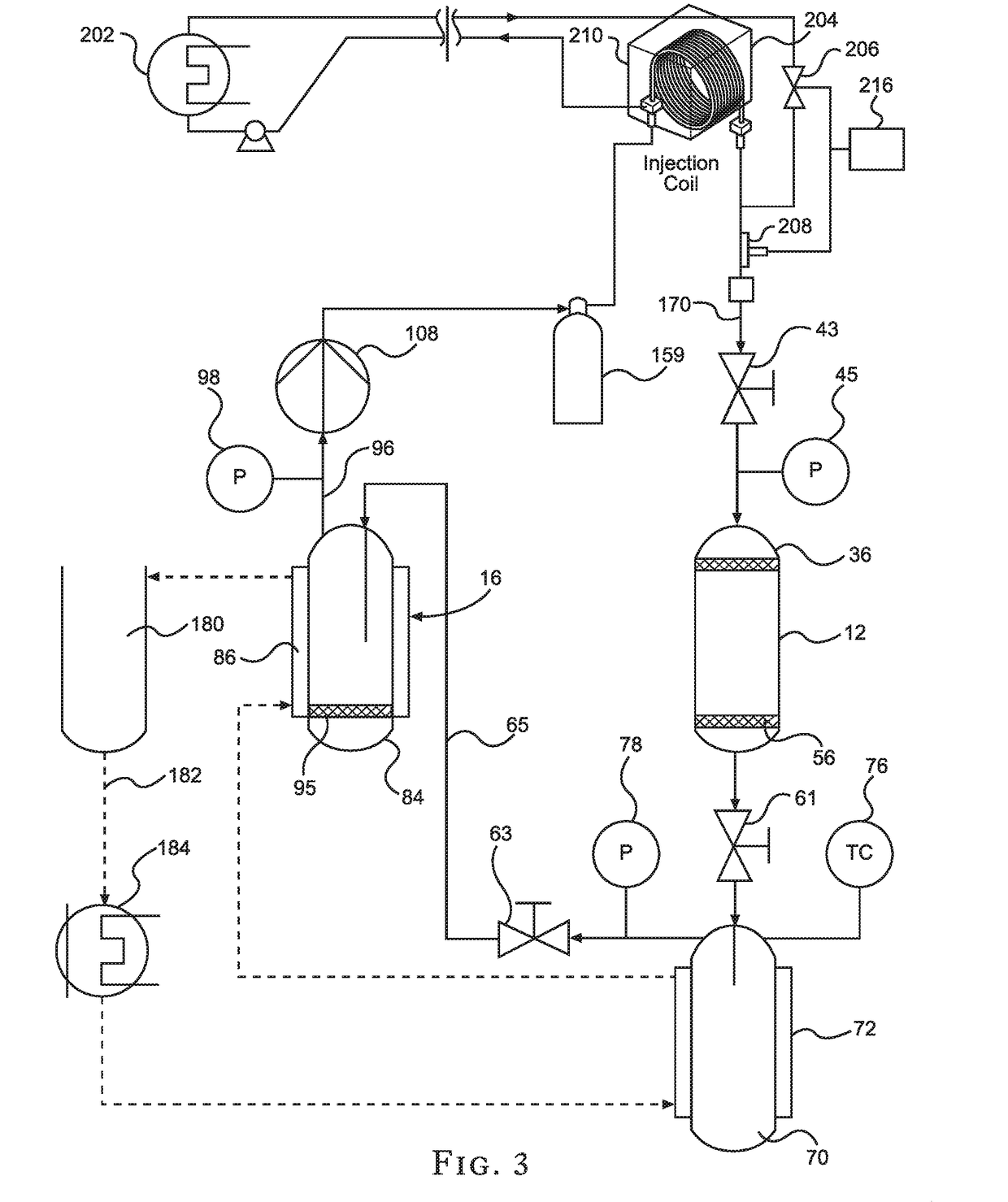
[0032]Turning now to the drawings in more detail, numeral 10 designates the system of plant oil extraction according to this invention. The system 10 comprises an extraction assembly 12, a separator assembly 14, an expansion filter assembly 16, a solvent recovery assembly 18, and an upright support assembly 19, which supports the extraction assembly 12 and the expansion filter assembly 16. If desired, the support assembly 19 can also support the separator assembly 14.

[0033]The extraction assembly 12 comprises a tubular hollow extraction vessel 20 having an open top 22 and an open bottom 24. A peripheral flange 23 extends outwardly from the open top 22. A similar peripheral flange 25 extends outwardly from the open bottom 24.

[0034]A top cup 26 normally detachably engages with the open top 22. The top cup has an open bottom 28 that matches the size and configuration of the top open end 22 of the extraction vessel 20. The top cup 26 is provided with a peripheral flange 27 that matches ...


PUM


Abstract

A continuous-flow extraction system and method for extracting oil from oil-bearing plant parts, or biomass, with liquid-phase hydrocarbon solvent in a continuous process, providing more than one extraction vessel so that one or more extraction vessels can be cleared of exhausted biomass and reloaded with biomass, while another one or more extraction vessels are undergoing the extraction process, optionally providing a de-waxer for use when needed, providing a primary jacketed separator vessel for flashing hydrocarbon solvent to a vapor phase and precipitating and collecting liquid plant extract, providing at least one secondary jacketed separator vessel for purification and refinement of vapor-phase hydrocarbon solvent and providing for re-liquefication of the solvent for the purpose of re-circulating and reusing the solvent, and providing for the heating, cooling, and pumping necessary to carry out the various steps.

Description

CROSS-REFERENCE TO RELATED APPLICATIONS[0001]This application is a continuation-in-part of my co-pending application Ser. No. 15 / 190,977, filed on Jun. 23, 2016 for an “Apparatus for Extracting Oil from Oil-Bearing Plants,” which is a continuation-in-part of my previous application Ser. No. 14 / 470,494, filed on Aug. 27, 2014 for an “Apparatus for Extracting Oil from Oil-Bearing Plant Material,” issued as U.S. Pat. No. 9,399,180 on Jul. 26, 2016, which is a continuation-in-part of my previous application Ser. No. 13 / 734,915, filed on Jan. 4, 2013 (now abandoned), the full disclosures of which are hereby incorporated by reference and priority of which are hereby claimed.BACKGROUND OF THE INVENTION[0002]This invention is a continuous-flow extraction system and method for extracting oil from oil-bearing plant parts, or biomass, with liquid-phase hydrocarbon solvent, in a continuous process, with re-circulation and reuse of the solvent.[0003]Presently, such extraction is performed on a b...

Claims


Application Information

Patent Timeline
IPC IPC(8): C11B1/10
CPCC11B1/10B01D11/0203B01D11/0207B01D11/0215B01D11/028B01D11/0292B01D2011/007B01D11/00
Inventor ELLIS, MATTHEW
Owner ELLIS MATTHEW
Learn More