Coordinate-measuring machine

a technology of measuring machine and measuring plate, which is applied in the direction of measuring device, using optical means, instruments, etc., can solve the problems of difficult to ensure comparable measurements in this way, take a relatively large amount of time, and are highly time-consuming and prone to errors

Active Publication Date: 2017-08-31
CARL ZEISS IND MESSTECHN GMBH
View PDF5 Cites 2 Cited by
  • Summary
  • Abstract
  • Description
  • Claims
  • Application Information

AI Technical Summary

Benefits of technology

[0011]It is thus an object to provide a coordinate measuring machine which overcomes the above-stated disadvantages. It is particularly an object to adapt the light settings of the illumination device of the coordinate measuring machine in optimum fashion to the circumstances relating to the workpiece, without this resulting in a time-consuming process or requiring a large computational outlay.
[0018]Once the light conditions have been optimized for a reference workpiece, the above-mentioned procedure or principle makes it possible to reproduce said light conditions when measuring a subsequent workpiece of identical construction, without having to position the workpieces in a specific, predefined position and / or orientation in relation to the optical sensor. The light conditions consequently do not need to be adapted all over again in advance to the respective workpiece whenever new workpieces are measured, because the already known light conditions, which were optimized for a reference workpiece, can be used and merely need to be adapted to the new orientation and position of the workpiece that is to be measured. This simplifies the measuring procedure. Not only that, it also entails an enormous time saving. The necessary computational outlay is also reduced.
[0025]In this case, the light conditions are thus not adapted by way of an actual, physical movement of the illumination device, but by recreating the movement virtually by way of adapting the light intensity of the illumination segments. Compared to an adaptation by way of a physical movement of the illumination device, this has the advantage that no additional drive for moving the illumination device is necessary. Not only does this represent a cost saving, but it also has a positive effect with respect to the accuracy of the measurement. This is because any movement and generation of heat that is caused by an additional actuator in the measurement head of the coordinate-measuring machine and that could negatively affect the accuracy of the measurement can thus be avoided.
[0031]This refinement has the advantage that the colors of light of the individual illumination segments can likewise be regulated individually. This is advantageous in particular if the workpiece to be measured itself is colored, since in this case it is possible to improve the contrast by accordingly adapting the color of the light. It is to be understood that the above-described adaptation of the light intensity values can be performed accordingly even in the case of illumination segments having a plurality of differently colored illuminant. However, in this case the same number and the same type of illuminant are preferably used for each illumination segment.

Problems solved by technology

Matching the light setting of the illumination device in this fashion can at times take a relatively large amount of time.
The simplest approach, specifically that of performing the light settings separately for each workpiece by hand, is highly time-consuming and prone to errors.
Comparable measurements can hardly be ensured in this way.
However, the use of such clamping aids is costly and not practical either if the workpiece types frequently change.
However, it is to be understood that even an optimization method of this type is relatively time-consuming and likewise requires a relatively large computer-assisted computational outlay.

Method used


Image

  • Coordinate-measuring machine
  • Coordinate-measuring machine
  • Coordinate-measuring machine

Examples


Embodiment Construction

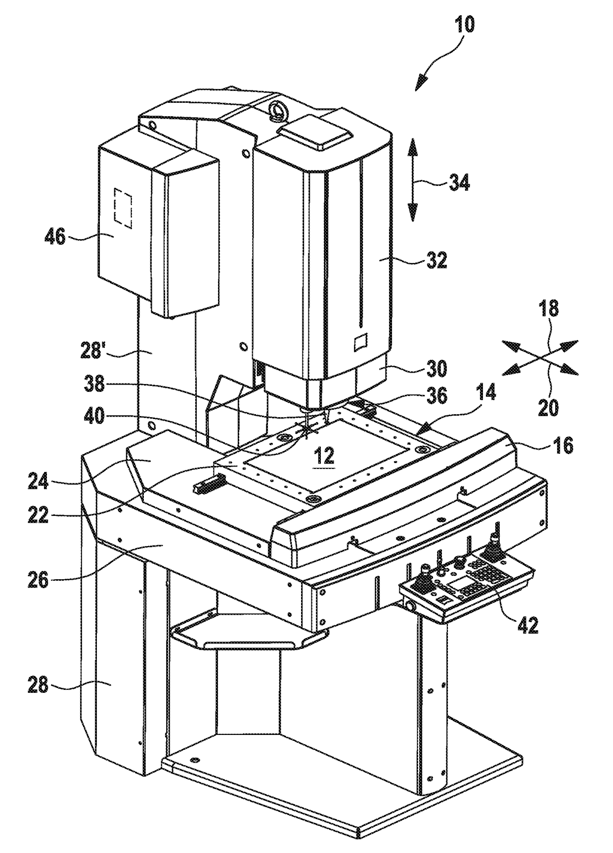
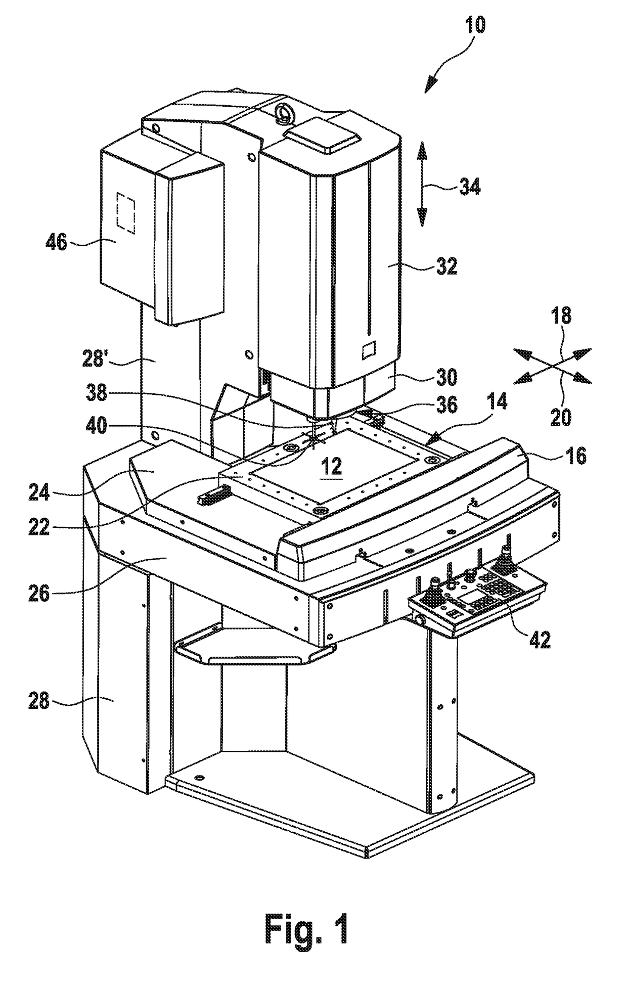
[0045]FIG. 1 shows a coordinate measuring machine according to an exemplary embodiment of the present disclosure. The coordinate measuring machine as a whole is here denoted with the reference numeral 10.

[0046]The coordinate measuring machine 10 has a workpiece holder 12, on which the workpiece to be measured can be placed. This workpiece holder 12 is arranged on a measurement table 14. Depending on the embodiment of the coordinate measuring machine, said measurement table can be a fixed, that is to say a non-moving measurement table. However, in the embodiment illustrated in FIG. 1, the measurement table 14 is one which is linearly displaceable along two mutually orthogonal coordinate axes 18, 20 in the measurement table plane using a positioning device 16. The first coordinate axis 18 is normally referred to as the x-axis, and the second coordinate axis 20 is normally referred to as the y-axis.

[0047]In the exemplary embodiment of the coordinate measuring machine 10 shown in FIG. 1...


PUM


Abstract

A coordinate measuring machine comprising an optical sensor for optically capturing a workpiece; an illumination device for illuminating the workpiece; a pose determination unit for determining data relating to a workpiece pose including a position and orientation of the workpiece; a storage unit for storing (i) data relating to a reference pose including a position and orientation of a reference workpiece, and (ii) data relating to a reference light setting of the illumination device used for a measurement of the reference workpiece; and a control unit which is configured to control a light setting of the illumination device for a measurement of the workpiece by adapting the reference light setting based on a comparison of the stored data relating to the reference pose with the determined data relating to the workpiece pose.

Description

CROSS-REFERENCES TO RELATED APPLICATIONS[0001]This application claims priority from German patent application DE 10 2016 103 557.2, filed on Feb. 29, 2016. The entire content of this priority application is incorporated herein by reference.BACKGROUND OF THE INVENTION[0002]The present disclosure relates to a coordinate measuring machine, in particular to an optical coordinate measuring machine, having an optical sensor for optically capturing a workpiece to be measured, an illumination device for illuminating the workpiece to be measured, and a pose determination unit for determining data relating to the position and orientation of the workpiece to be measured.[0003]An exemplary coordinate-measuring machine of this type is known for example from DE 101 40 174 A1 and DE 10 2012 103 554 A1.[0004]Coordinate measuring machines serve for checking workpieces, for example as part of quality assurance, or for ascertaining the geometry of a workpiece as part of what is known as “reverse engin...

Claims


Application Information

Patent Timeline
Patent Type & Authority Applications(United States)
IPC IPC(8): G01B11/00
CPCG01B11/005G01B21/047
Inventor DOTSCHKAL, FLORIANRIEGER, STEPHAN
Owner CARL ZEISS IND MESSTECHN GMBH
Why Eureka
Try Eureka