Position detection device

Inactive Publication Date: 2017-08-31
DENSO CORP
View PDF1 Cites 0 Cited by
  • Summary
  • Abstract
  • Description
  • Claims
  • Application Information

AI Technical Summary

Benefits of technology

[0008]In the position detection device thus configured, the magnetic field detection surface is formed to include the two X-axis-direction sides, the two Y-axis-direction sides, and the fourth connection sides each shaped as the arc or line. Accordingly, when the position in the Y-axis direction is changed in the state where the position in the X-axis direction is fixed in the position detection device in the present disclosure, a change in the X-axis-direction component of the magnetic field resulting from the position change in the Y-axis direction can be reduced.
[0009]As a result, it is possible to calculate the position of the magnet in the X-axis direction on the basis of the X-axis-direction component of the magnetic field detected by the magnetic field detector without using the Y-axis-direction component of the magnetic field detected by the magnetic field detector.
[0010]Likewise, when the position in the X-axis direct

Problems solved by technology

However, since the distribution of the magnetic field generated by the magnet attached to the movable part is complicated, sophisticated arithmetic operat

Method used


Image

  • Position detection device
  • Position detection device
  • Position detection device

Examples


Example

[0034]The following will describe a first embodiment of the present disclosure in association with the drawings.

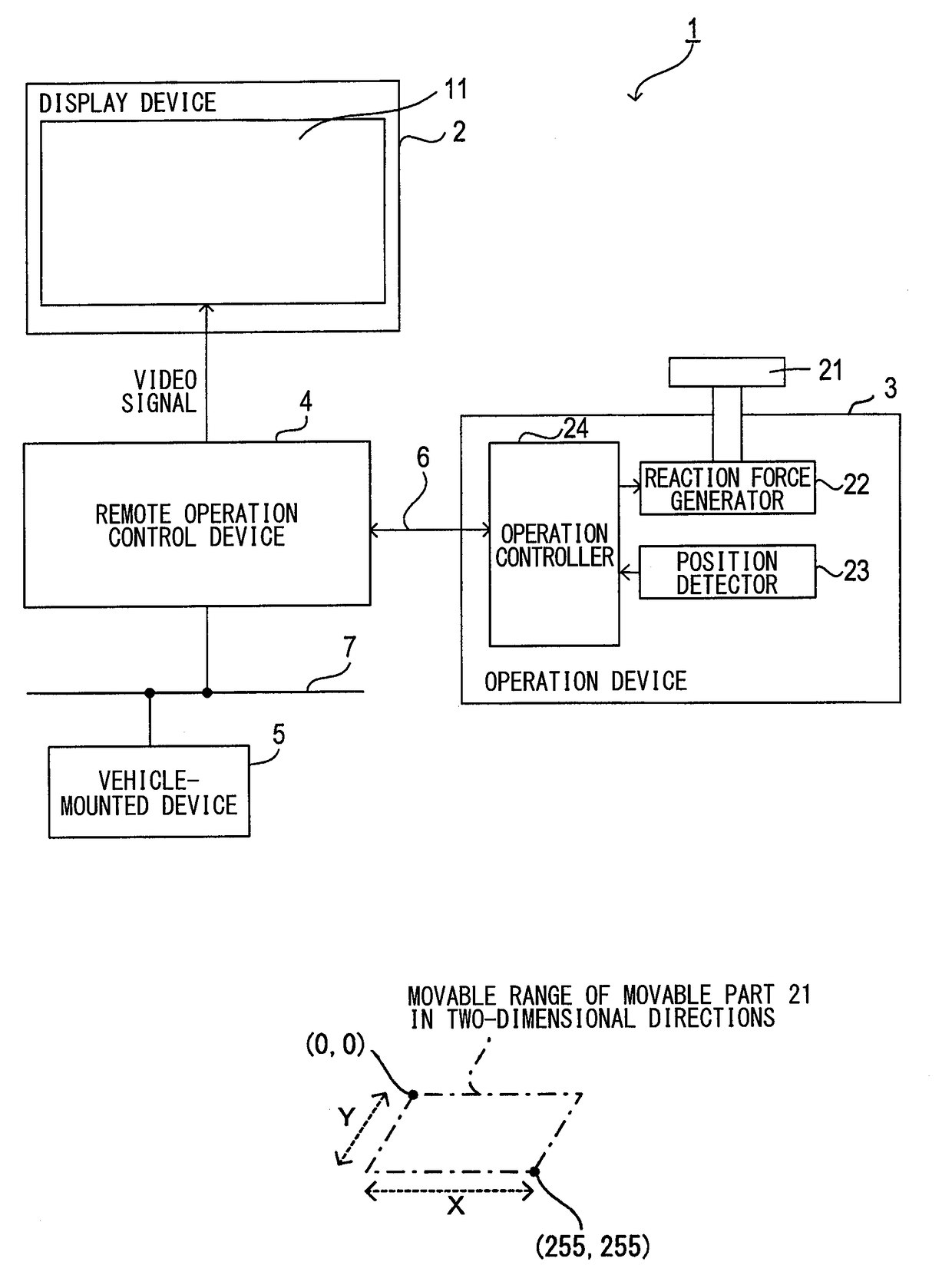
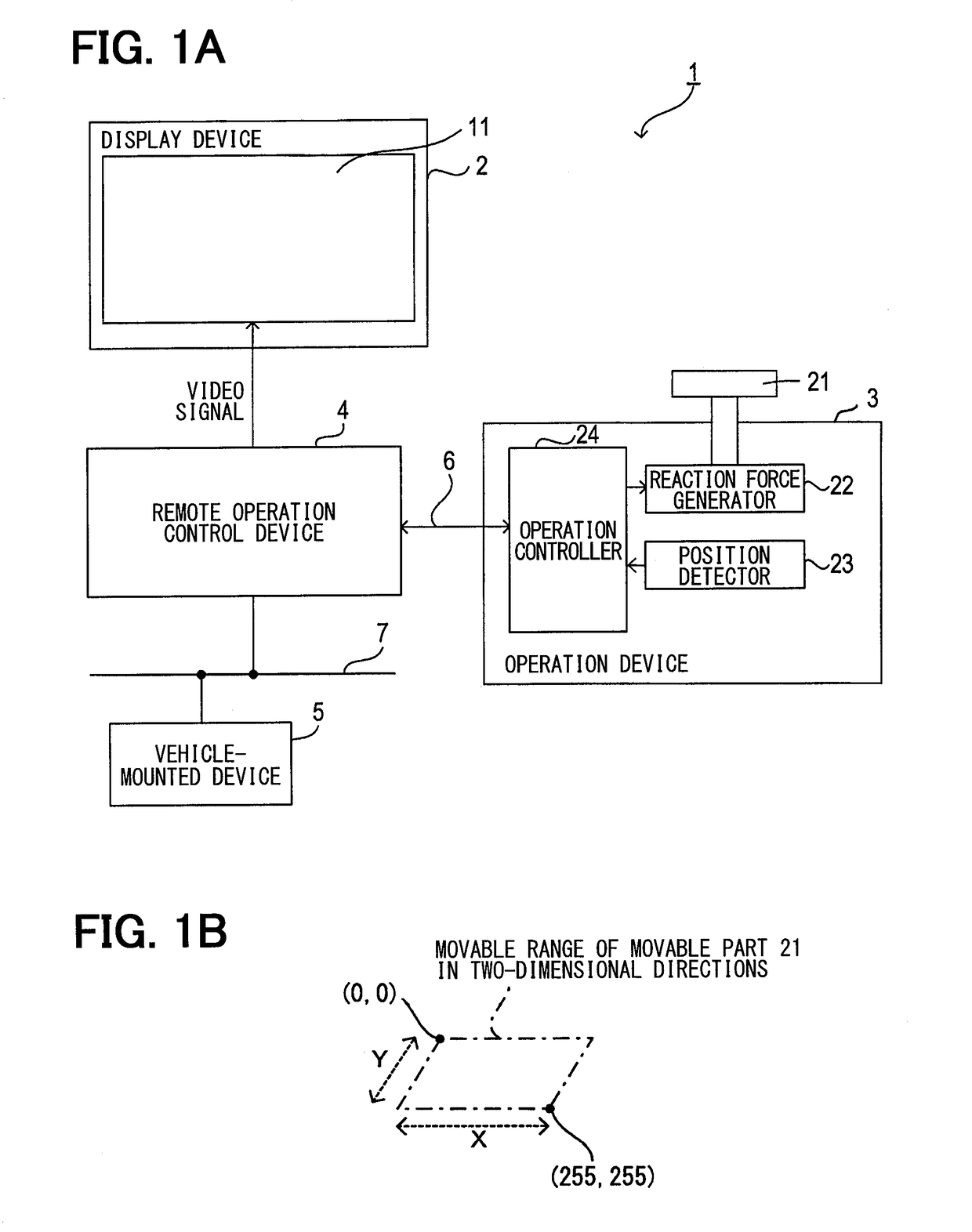
[0035]A remote operation system 1 in the present embodiment is mounted in a vehicle and includes a display device 2, an operation device 3, a remote operation control device 4, and a vehicle-mounted device 5 (such as, e.g., a navigation device, an audio device, or an air conditioning device), as shown in FIG. 1A.

[0036]The display device 2 is a color display device having a display screen 11 such as a liquid crystal display and displays various images on the display screen 11 in accordance with a video signal input thereto from the remote operation control device 4.

[0037]The display device 2 is disposed at a middle position between a driver seat and a passenger seat on a dashboard (not shown) located in front of a driver in a vehicle interior. This reduces the eye movement of the driver when the driver looks at the display screen 11 of the display device 2.

[0038]The operati...

Example

Second Embodiment

[0108]The following will describe a second embodiment in the present disclosure in association with the drawings. Note that, in the second embodiment, a portion different from that in the first embodiment is described.

[0109]The remote operation system 1 in the second embodiment is different from that in the first embodiment in that the magnet 51 has been changed.

[0110]As shown in FIG. 12A, the magnet 51 in the second embodiment is formed in a generally rectangular shape in which the respective end portions of the X-axis-direction sides 61 and 62 and the respective end portions of the Y-axis-direction sides 63 and 64 are connected by lines.

[0111]Specifically, the magnet 51 is formed to have the magnetic field detection surface 70 including the X-axis-direction sides 61 and 62, the Y-axis-direction sides 63 and 64, and the connection sides 65, 66, 67, and 68.

[0112]The connection side 65 shaped as a line connects the end portion of the X-axis-direction side 61 and the ...


PUM


Abstract

An operation device includes a movable part movable in X- and Y-axis directions, a magnet movable integrally with the movable part, and a magnetic field sensor detecting a magnetic field of the magnet. The magnet includes a magnetic field detection surface including X-axis-direction sides, Y-axis-direction sides, and connection sides. The X-axis-direction sides are parallel with each other along the X-axis direction. The Y-axis-direction sides are parallel with each other along the Y-axis direction. The connection sides each shaped as an arc or a line connect respective end portions of the X-axis-direction sides and respective end portions of the Y-axis-direction sides. The magnetic field detection surface is line-symmetric with respect to respective lines parallel with the X- and Y-axis directions. The magnetic field sensor is opposed to the magnetic field detection surface and detects respective components of a magnetic flux density of the magnet in the X- and Y-directions.

Description

CROSS REFERENCE TO RELATED APPLICATION[0001]This application is based on Japanese Patent Application No. 2014-175904 filed on Aug. 29, 2014, the disclosure of which is incorporated herein by reference.TECHNICAL FIELD[0002]The present disclosure relates to a position detection device which detects the position of a movable part capable of moving in an X-axis direction and a Y-axis direction which are orthogonal to each other.BACKGROUND ART[0003]Conventionally, a device has been known which includes a movable part capable of moving in an X-axis direction and a Y-axis direction which are orthogonal to each other, a magnet attached to the movable part, and a magnetic sensor which detects a magnetic field generated by the magnet. The device is configured to be able to detect the position of the movable part (see, e.g., Patent Literature 1).PRIOR ART LITERATUREPatent Literature[0004]Patent Literature 1: JP2013-103668ASUMMARY OF INVENTION[0005]However, since the distribution of the magneti...

Claims


Application Information

Patent Timeline
IPC IPC(8): G01D5/12
CPCG06F3/046G01D5/12G01R33/02G01D5/145
Inventor HATANAKA, SHINJITACHIIRI, MOTOKI
Owner DENSO CORP
Why Eureka
Try Eureka