Miniaturized dual-polarized base station antenna

a base station antenna and dual-polarization technology, applied in the direction of antennas, polarised antenna unit combinations, antenna details, etc., can solve the problems of complex manufacturing of such antennas, one complex feeding network is required, and the problem of square dipoles having a major defect, so as to improve the front-to-back ratio and the cross polarization ratio.

Active Publication Date: 2017-08-31
GUANGZHOU SIGTENNA TECH CO LTD
View PDF0 Cites 12 Cited by
  • Summary
  • Abstract
  • Description
  • Claims
  • Application Information

AI Technical Summary

Benefits of technology

[0016]In addition, the reflecting plate of the antenna of the present application is much smaller than the reflecting plate of the existing known antennas. The radiation device is placed on this small-size reflecting plate. The radiation device includes an additional conductor element which is located between ends of the adjacent folded oscillators, and another conductor element is located on the geometric center of the radiation conductor. Those additional conductors improve the front-to-back ratio and the cross polarization ratio on one hand, and on the other hand, when the radiation device is placed on one small-size reflecting plate, those additional elements are matched with the coaxial feeding network.

Problems solved by technology

Such square dipoles have a major defect that one complex feeding network is required, for example, the four single-dipoles must be respectively fed by four coaxial cables.
Although it is a novel graphic structure, it is still very complex to manufacture such antennas.

Method used


Image

  • Miniaturized dual-polarized base station antenna
  • Miniaturized dual-polarized base station antenna
  • Miniaturized dual-polarized base station antenna

Examples


first embodiment

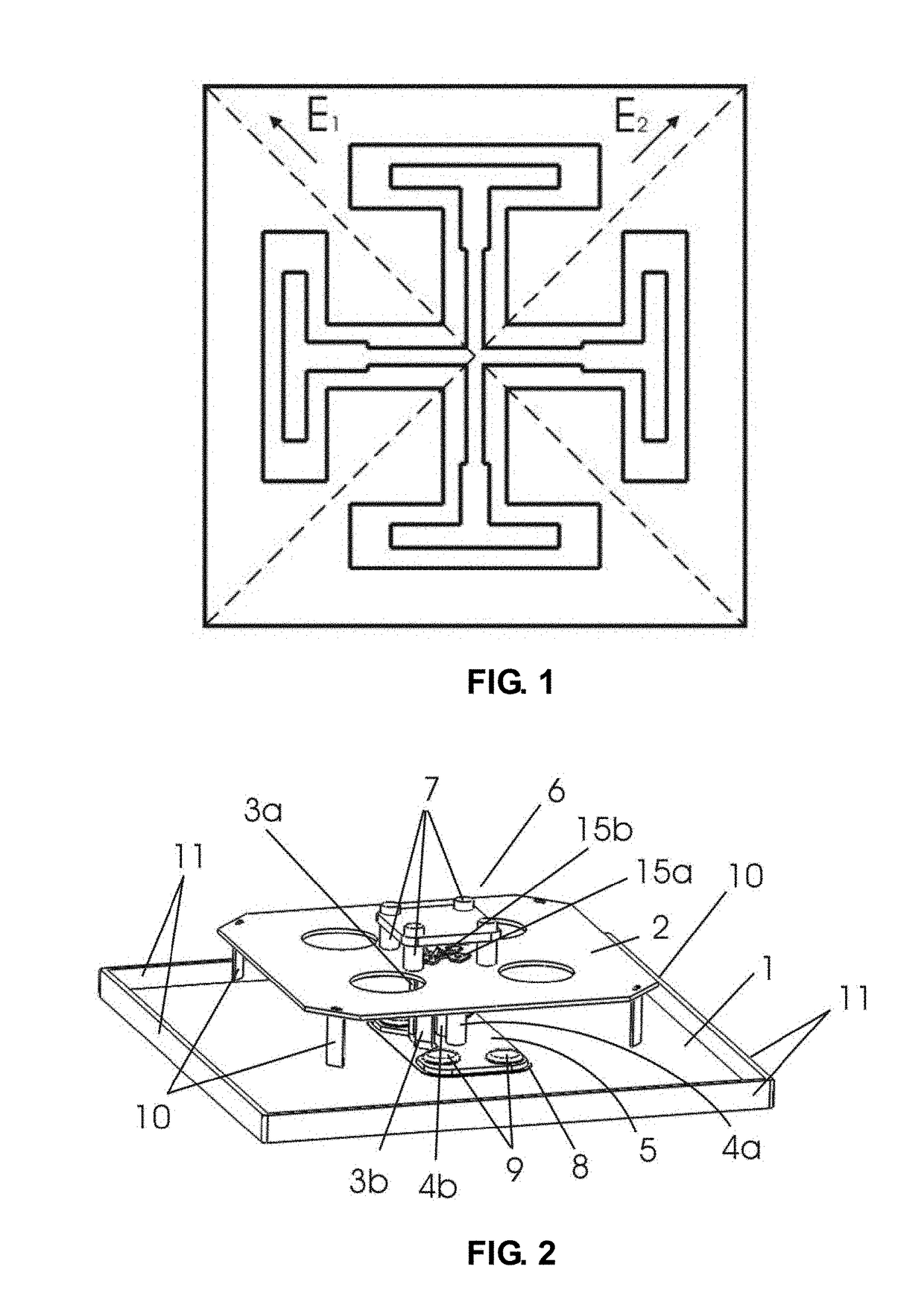
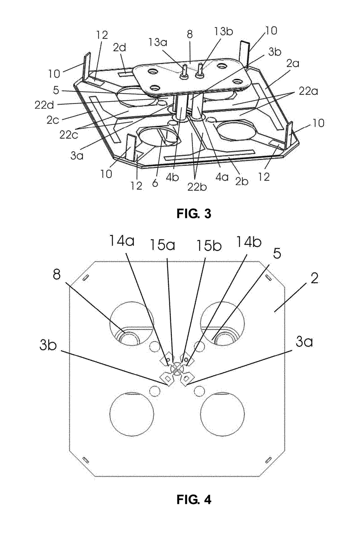
[0025]FIG. 2 shows the present application. A radiation device manufactured from a printed circuit board, and two vertical baluns supported on the reflecting plate 1 are included. The reflecting plate 1 is much smaller than the reflecting plate of the existing known antennas. Four folded oscillators 2a, 2b, 2c and 2d are fed by four groups of symmetric striplines 22a, 22b, 22c and 22d which are placed on a bottom surface of a medium substrate 2, as shown in FIG. 3. A support conductor 3a and an outer conductor 4a of the coaxial cable are connected to a metal base plate 5 to form a first balun. Similarly, the second balun is formed by connecting a support conductor 3b and an outer conductor 4b of the coaxial cable to the metal base plate 5, and the support conductors 3a and 3b are less than 0.15 wavelengths of the center working frequency thereof. Bottom ends of the support conductors 3a and 3b are connected to the outer conductors 4a and 4b by a conductor base plate 5, a top conduct...

second embodiment

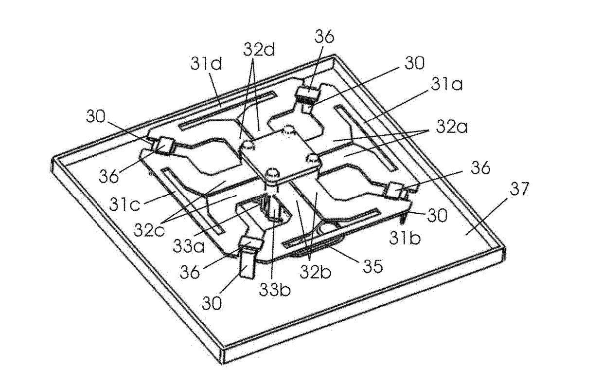
[0032]FIG. 5 shows the present application. The radiation device includes four folded oscillators 31a, 31b, 31c and 31d which are connected to the symmetric striplines 32a, 32b, 32c and 32d of the folded oscillators, and two vertical baluns which are cast into a body by die-casting. The first balun consists of a support conductor 33a, outer conductors of coaxial cables, and a base plate 35 connecting them together.

[0033]Conductors 30 are supported between ends of the adjacent folded oscillators by an insulating medium gasket 36, and each conductor 30 is bent to a right angle. A part of each of the conductors 30 is secured in the insulating medium gasket 36, while the other part thereof is directed to the reflecting plate 37. Hence, the conductors 30 function as the conductors 10 and 12 in FIG. 4. The second embodiment of the present application as shown in FIG. 5 has the same advantages as the first embodiment. However, this embodiment is applicable to massive production, with lower...


PUM


Abstract

The present invention discloses a miniaturized dual-polarized base station antenna, comprising a radiation device and a feeding unit. The feeding unit comprises two coaxial cables and two vertical baluns consisting of two conductors, and the radiation device is supported on a reflecting plate. The radiation device consists of four crossed oscillators and four groups of symmetric striplines, and the four groups of symmetric striplines are in the center of the radiation device and connected to the crossed oscillators and feed the four crossed oscillators in a matched manner. In the center of the radiation device, the adjacent conductors of the four groups of symmetric striplines are connected to each other to form an end-to-end connected closed conductor ring, and a top conductor sheet on the center of the radiation device is a square or circular metal member.

Description

FIELD OF THE INVENTION[0001]The present invention relates to a dual-polarized directional transceiver antenna having a horizontal lobe width of 55° to 75°, the two polarizations of which are orthogonal, for example, orthogonal horizontal and vertical polarizations or ±45° inclined polarizations.BACKGROUND OF THE INVENTION[0002]U.S. Pat. No. 3,740,754 is one of the earliest patents in which a dual-polarized antenna is described. This patent describes an oscillator consisting of two metal tubes which are connected to each other along a proper folding line and placed on a one reflecting cup, and the two groups of oscillators are respectively fed by two groups of coaxial cables. Subsequently, in order to extend the working band thereof, hundreds of different dual-polarized antennas have been developed.[0003]U.S. Pat. No. 4,184,163 describes a broadband dual-polarized antenna. In this patent, the oscillator arm of the antenna consists of a metal ring which is in a finger ring shape or a ...

Claims


Application Information

Patent Timeline
Patent Type & Authority Applications(United States)
IPC IPC(8): H01Q1/24H01Q25/00H01Q19/10H01Q21/26
CPCH01Q1/246H01Q19/10H01Q25/00H01Q21/26H01Q25/001
Inventor LI, ZIMENG
Owner GUANGZHOU SIGTENNA TECH CO LTD
Why Eureka
Try Eureka