Reinforcement for a concrete tile

a technology of reinforcement and concrete, applied in the field of concrete elements, can solve the problems of difficult optimal process and achieve the effect of convenient positioning

Active Publication Date: 2017-09-07
LE SQUAREDECKO
View PDF5 Cites 2 Cited by
  • Summary
  • Abstract
  • Description
  • Claims
  • Application Information

AI Technical Summary

Benefits of technology

[0007]To provide for a way to install a reinforcement for a concrete tile which is easy to position while providing an excellent means of reinforcement.

Problems solved by technology

Typically, whether in the case of reinforced concrete or ferro-cement, careful positioning of the steel armature as well as ensuring that the armature does not move during the compacting and vibrating of the concrete makes the process rather difficult to achieve in an optimal way and only highly trained and skilled artisans can produce a consistently good piece of decorative concrete.

Method used


Image

  • Reinforcement for a concrete tile
  • Reinforcement for a concrete tile
  • Reinforcement for a concrete tile

Examples


example

[0045]A load-deflection curve for a 10″×16″ tile with a thickness of 1 inch produced by a dry cast technique and having a compression strength of between 45 and 60 MPa and comprising 2 reinforcement inserts was obtained using a constant rate extension dynamometer. Diameter of loading disc: 3 inches. Diameter of bag drop: 9.5 inches. Impact located in middle of tile. Weight of bag drop: 13.6 Kg. Speed of displacement for deflection: 5 mm / min. Results are shown in FIG. 6.

[0046]A load-deflection curve for a 16″×20″ tile with a thickness of 1¼ inch produced by a wet cast technique and having a compression strength of between 30 and 45 MPa and comprising 3 reinforcement inserts was obtained using a constant rate extension dynamometer. Diameter of loading disc: 3 inches. Diameter of bag drop: 9.5 inches. Impact located in middle of tile. Weight of bag drop: 13.6 Kg. Speed of displacement for deflection: 5 mm / min. Results are shown in FIG. 7.


PUM

PropertyMeasurementUnit
thicknessaaaaaaaaaa
thicknessaaaaaaaaaa
heightaaaaaaaaaa

Abstract

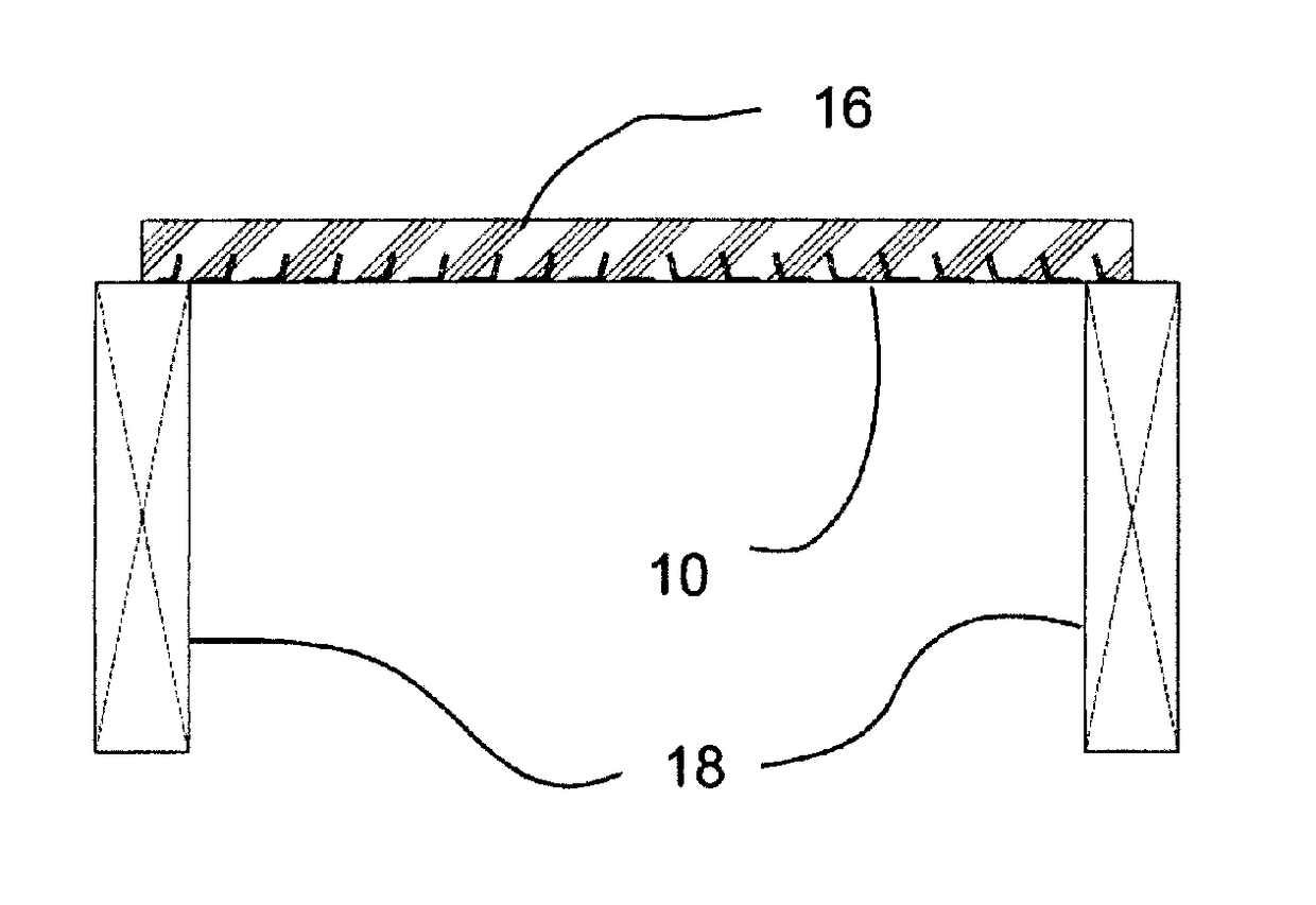
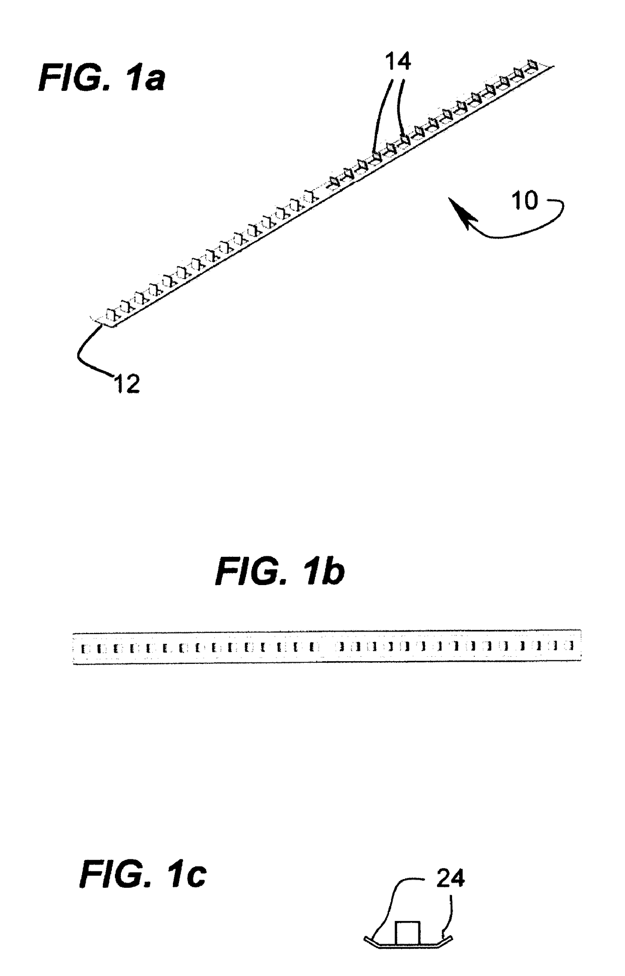
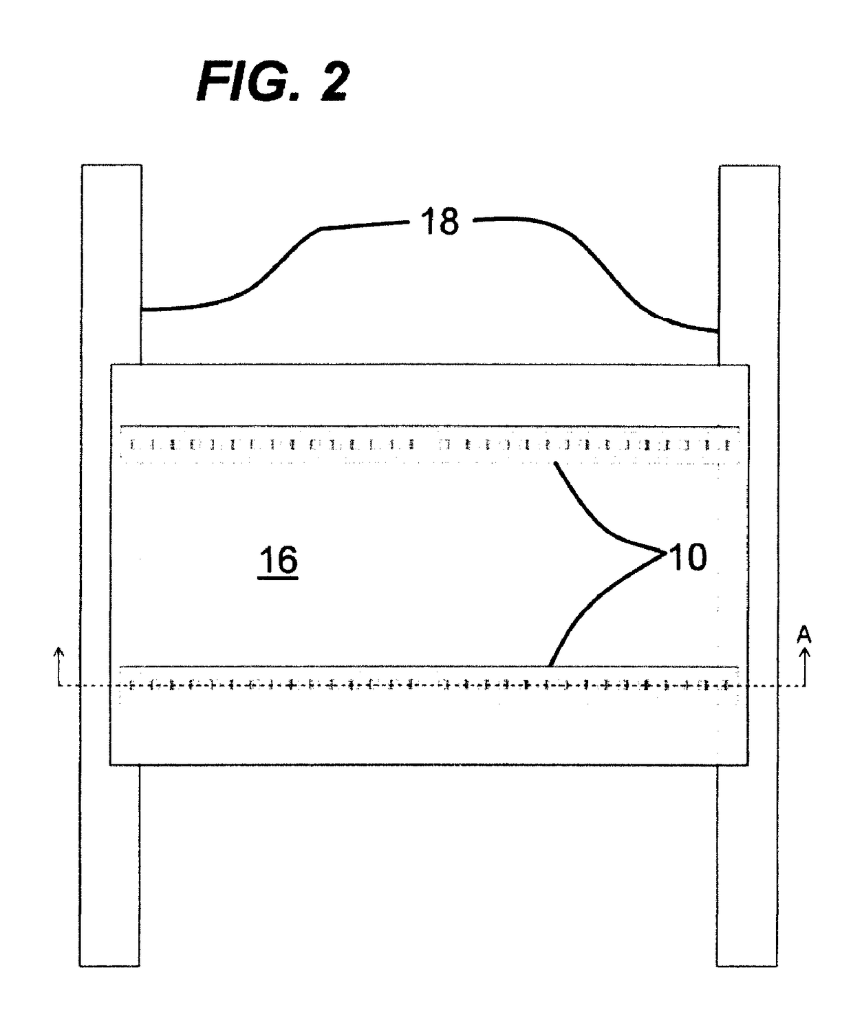
A reinforced concrete tile having top and bottom surfaces defining a thickness, the reinforced concrete tile comprising two or more reinforcing inserts imbedded in the concrete tile in proximity to the bottom surface, the two or more reinforcing inserts being of elongated shape and comprising a plurality of scales distributed along the length and extending upwardly from the bottom surface whereby a compensating force is created upon application of a load on the top surface such that deflection is reduced as the load is increased for at least a range of loads until a yield load is reached.

Description

[0001]This application is a continuation-in-part of U.S. patent application Ser. No. 14 / 428,028 filed Mar. 13, 2015, now pending, that is a national stage of PCT / CA2013 / 000778 filed Sep. 13, 2013, now abandoned, that claims priority of U.S. provisional patent application 61 / 700,090 filed Sep. 14, 2012.FIELD OF THE INVENTION[0002]The present invention relates generally to concrete elements but more particularly to a reinforcement for a concrete tile.BACKGROUND OF THE INVENTION[0003]Concrete tiles used as a decorative element for pavement, patios, walkways, etc are quite popular. Typically, no steel reinforcement are within the concrete as the products are placed directly on the ground. Sometimes, when they need to put concrete over a structure, manufacturer will decide to increase thickness of the product or, they use a steel reinforcement grid placed within. Generally midway or the lower third of the thickness of the concrete. There is also a technique known as ferro-cement which co...

Claims


Application Information

Patent Timeline
Patent Type & Authority Applications(United States)
IPC IPC(8): E04C2/06G01N33/38E04B5/02G01N3/02E04B5/12E04C2/28
CPCE04C2/06E04B5/12G01N33/383E04C2/50G01N3/02E04C2/28G01N2203/0023G01N2203/0064E04C2/04E04C2002/046
Inventor OUELLET, ANDRE
Owner LE SQUAREDECKO
Why Eureka
Try Eureka