
Flow angle probe

Inactive Publication Date: 2017-09-07
VETCO GRAY SCANDINAVIA
View PDF4 Cites 1 Cited by
  • Summary
  • Abstract
  • Description
  • Claims
  • Application Information

AI Technical Summary

Benefits of technology

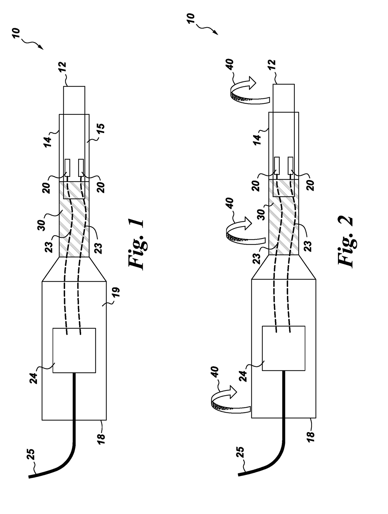
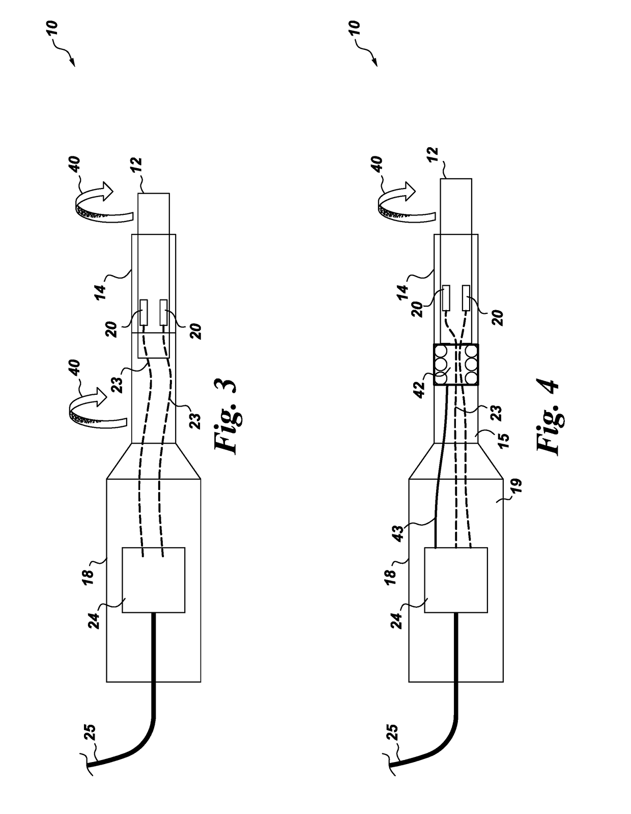
The present invention provides a flow angle probe that can measure the angle at which a fluid flows through a conduit. The probe flap is designed to contact the fluid and deflect it, creating a force that is sensed by a force sensor. By rotating the probe flap to a position where it is not being deflected by the fluid, the sensed force can be minimized. This allows for accurate measurement of the fluid flow angle even when the fluid is in motion. The invention is useful in a variety of applications where measuring the flow angle of a fluid is important.

Problems solved by technology

While flow angles may be estimated for various equipment systems using computational fluid dynamics tools, real-time monitoring of fluid flow angles within fluid processing equipment can be challenging, especially when the fluid in question is a multiphase fluid.
While flow angle measurement devices and systems are known for use in measuring the flow angle characteristics of single phase fluids, devices and systems capable of reliably measuring flow angle characteristics of multiphase fluids are currently unknown.

Method used


Image

  • Flow angle probe
  • Flow angle probe
  • Flow angle probe

Examples


Embodiment Construction

[0021]In the following specification and the embodiments, which follow, reference will be made to a number of terms, which shall be defined to have the following meanings.

[0022]The singular forms “a”, “an”, and “the” include plural referents unless the context clearly dictates otherwise.

[0023]“Optional” or “optionally” means that the subsequently described event or circumstance may or may not occur, and that the description includes instances where the event occurs and instances where it does not.

[0024]Approximating language, as used herein throughout the specification and embodiments, may be applied to modify any quantitative representation that could permissibly vary without resulting in a change in the basic function to which it is related. Accordingly, a value modified by a term or terms, such as “about” and “substantially”, are not to be limited to the precise value specified. In at least some instances, the approximating language may correspond to the precision of an instrumen...


PUM


Abstract

A flow angle probe is provided having (a) a probe flap for contacting a moving fluid within a fluid conduit; (b) a probe body mechanically coupled to the probe flap; (c) a force sensor disposed within the probe body and operationally coupled to the probe flap; and optionally (d) a probe shaft coupled to the probe body. A deflection of the probe flap caused by contact with the moving fluid produces a corresponding force sensor signal output which is minimized by rotation of the probe flap. The angle between this point of minimum deflection and a reference position is taken to be the flow angle of the moving fluid in the vicinity of the probe flap. The novel flow angle probes disclosed herein may be used in a wide variety of turbomachines and fluid processing systems, and applications, including turbomachine design and operational control, and in flow assurance.

Description

CROSS REFERENCE TO RELATED APPLICATIONS[0001]The present application claims priority to U.S. provisional application No. 62 / 302,246 filed Mar. 2, 2016 and which is incorporated by reference herein in its entirety.BACKGROUND[0002]The present invention relates to devices useful for measuring characteristics of a fluid flowing within a conduit. In particular, the present invention provides novel flow angle probes and systems containing them. Such flow angle probes may be used to detect the flow angle characteristics of a fluid flowing within a conduit.[0003]Understanding the flow angle characteristics of a fluid moving within a fluid conduit of fluid processing equipment such as pumps and compressors can be used to optimize both equipment design and performance. While flow angles may be estimated for various equipment systems using computational fluid dynamics tools, real-time monitoring of fluid flow angles within fluid processing equipment can be challenging, especially when the flui...

Claims


Application Information

Patent Timeline
IPC IPC(8): G01P13/00
CPCG01P13/0053G01P13/0006G01P13/002G01P13/0033G01P13/0026
Inventor HERRIG, ANDREASSCHNEIDER, CARSTEN MICHAELMELE, ERIKASHAR, SIDDHARTH NAVINCHANDRA
Owner VETCO GRAY SCANDINAVIA
Learn More