High frequency coil and magnetic resonance image pickup device

a pickup device and high frequency coil technology, applied in the field of magnetic resonance imaging (mri) apparatus, can solve the problems of reducing the magnetic coupling as far as possible, unable to achieve clear images, and completely eliminating magnetic coupling, so as to achieve high image quality and large and deep sensitivity area.

Active Publication Date: 2017-09-07
FUJIFILM HEALTHCARE CORP
View PDF5 Cites 4 Cited by
  • Summary
  • Abstract
  • Description
  • Claims
  • Application Information

AI Technical Summary

Benefits of technology

[0015]According to the present invention, in an RF coil of an MRI apparatus, multi-channel characteristic is reconciled with a large and deep sensitivity area, and an image of high image quality can be obtained.

Problems solved by technology

Therefore, for a deep part of imaging subject, it is difficult to obtain a clear image.
Further, the elimination of magnetic coupling performed for realizing an array coil reduces magnetic coupling as far as possible, and does not completely eliminate magnetic coupling.
Therefore, in a combination of subcoils disposed at a position where magnetic coupling strongly generates, not a little magnetic coupling remains, and performance of the array coil degrades.
However, such magnetic coupling elimination means themselves actually give a certain extent of loss.
In the case of a supermulti-channel array coil, it is necessary to remove magnetic coupling with a plurality of subcoils, and therefore configuration becomes complicated.

Method used


Image

  • High frequency coil and magnetic resonance image pickup device
  • High frequency coil and magnetic resonance image pickup device
  • High frequency coil and magnetic resonance image pickup device

Examples


first embodiment

[0035]The first embodiment of the present invention will be explained below. In the following descriptions, components having the same functions are referred to with the same numerals or codes in all the drawings for explaining the embodiments of the present invention, and repetition of explanations thereof is omitted.

[0036][Configuration of MRI Apparatus]

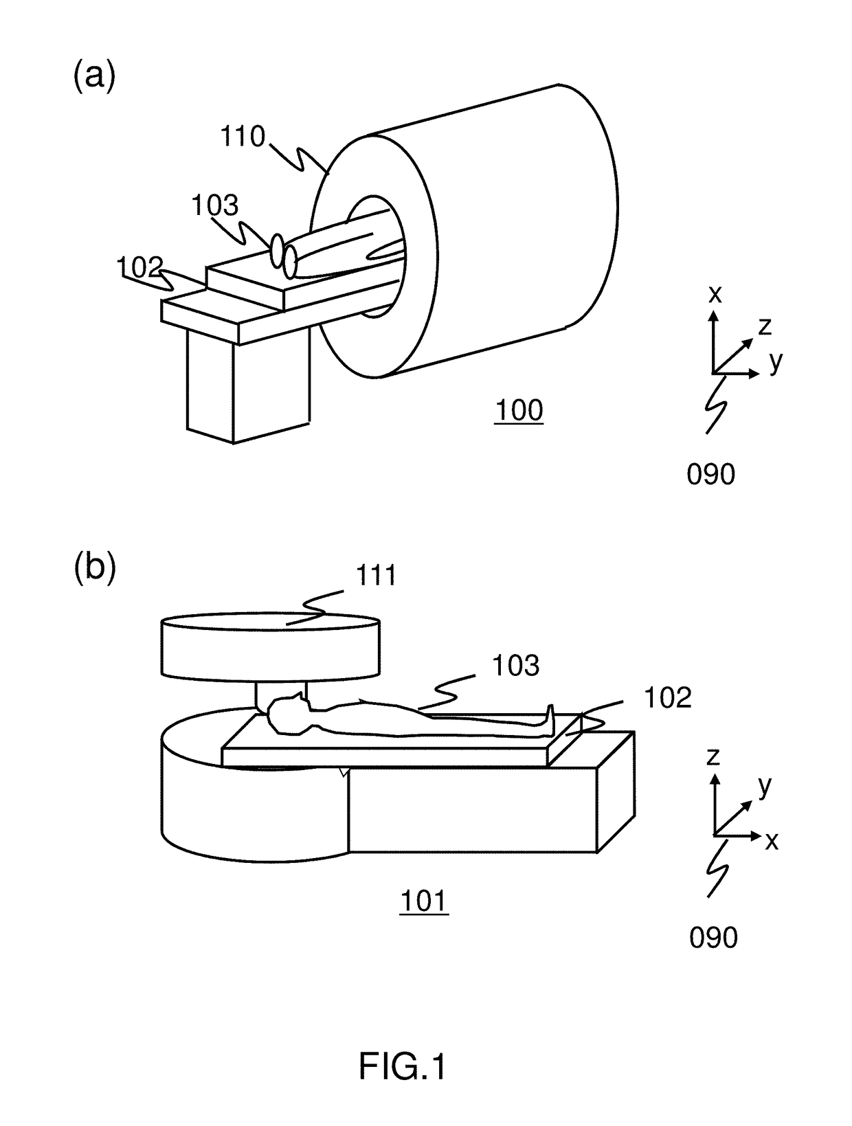
[0037]First, configuration of the whole MRI apparatus of this embodiment will be explained with reference to FIG. 1. FIG. 1 includes external views of MRI apparatuses of this embodiment. FIG. 1a shows an MRI apparatus 100 of the horizontal magnetic field type using a tunnel type magnet that generates a static magnetic field with a solenoid coil. FIG. 1b shows an MRI apparatus 101 of the vertical magnetic field type using hamburger type magnets, which comprises separate upper and lower magnets for enhancing spaciousness. These MRI apparatuses 100 and 101 comprise a table 102, on which a test subject 103 is placed. This embodiment ca...

second embodiment

[0187]Hereafter, the second embodiment of the present invention will be explained. In the first embodiment, the array coil is constituted by a combination of two of subcoils. In this embodiment, an array coil is constituted by a combination of three or more subcoils to realize multi-channel characteristic, large sensitivity area, and high sensitivity, and an example thereof is explained. Use of a plurality of coils can improve the sensitivity.

[0188]The MRI apparatus of this embodiment basically has the same configuration as that of the MRI apparatus 100 of the first embodiment. Hereafter, this embodiment will be explained by focusing the explanation on configurations different from those of the first embodiment.

[0189]FIG. 16 is a drawing for explaining an array coil 700 of this embodiment. As shown in this drawing, the array coil 700 of this embodiment comprises a first subcoil 710A, second subcoil 710B, and third subcoil 710C. These are disposed in this order at such positions that...

third embodiment

[0209]Hereafter, the third embodiment of the present invention will be explained. In this embodiment, adjacent subcoils are disposed so that they partially overlap with each other to prevent magnetic coupling between the subcoils.

[0210]The MRI apparatus of this embodiment basically has the same configuration as that of the MRI apparatus 100 of the first embodiment. Hereafter, this embodiment will be explained by focusing the explanation on configurations different from those of the first embodiment.

[0211]FIGS. 17a and 17b are drawings for explaining an array coil 800 of this embodiment. Hereafter, this embodiment will be explained with reference to an example where the array coil 800 is constituted with five subcoils 810. However, the number of the subcoils 810 that constitute the array coil 800 is not limited to this number.

[0212]The array coil 800 comprises a first subcoil 810A, fourth subcoil 810D, second subcoil 810B, fifth subcoil 810E, and third subcoil 810C from the top.

[0213...


PUM


Abstract

A technique for reconciling large sensitivity area and high sensitivity for deep part in a multi-channel array coil of an MRI apparatus without complicating the configuration, and realizing both higher speed imaging and high image quality is provided. An RF coil (array coil) of a magnetic resonance imaging apparatus comprising a plurality of subcoils is provided. At least one of the subcoils is a first subcoil of which resonance frequency as that of the subcoil alone differs from magnetic resonance frequency. The first subcoil is adjusted so that it magnetically couples with a second subcoil, which is at least one other subcoil, and thus resonates at the same frequency as the magnetic resonance frequency. Input and output terminals of the first subcoil and the second subcoil are connected to different low input and output impedance signal processing circuits, respectively.

Description

TECHNICAL FIELD[0001]The present invention relates to a magnetic resonance imaging (MRI) apparatus, in particular, an RF coil (Radio Frequency Coil, high-frequency coil) for irradiating a radio frequency magnetic field and detecting a magnetic resonance signal.BACKGROUND ART[0002]MRI apparatuses are imaging apparatuses for imaging an arbitrary section of an imaging subject using the nuclear magnetic resonance phenomenon. Specifically, MRI apparatuses irradiate a radio frequency magnetic field on an imaging subject placed in a spatially uniform magnetic field (static magnetic field) to cause magnetic resonance, detect generated magnetic resonance signals, and perform image processing for the detected signals to obtain a tomographic image.[0003]A device that irradiates a radio frequency magnetic field on an imaging subject and detects magnetic resonance signals generated from the imaging subject is called RF coil. The RF coil has a loop part (coil loop) for performing the irradiation ...

Claims


Application Information

Patent Timeline
Patent Type & Authority Applications(United States)
IPC IPC(8): G01R33/34G01R33/3815A61B5/055G01R33/36G01R33/54
CPCG01R33/34G01R33/3635G01R33/3815A61B5/055G01R33/54G01R33/34076G01R33/3415G01R33/3642G01R33/365G01R33/3657
Inventor OTAKE, YOSUKEOCHI, HISAAKIIWASAWA, KOHJIRO
Owner FUJIFILM HEALTHCARE CORP
Why Eureka
Try Eureka