Developing sleeve and developing device
- Summary
- Abstract
- Description
- Claims
- Application Information
AI Technical Summary
Benefits of technology
Problems solved by technology
Method used
Image
Examples
first embodiment
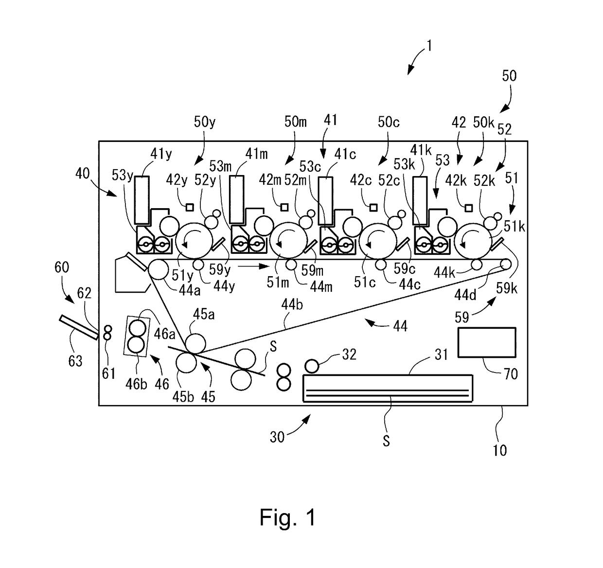
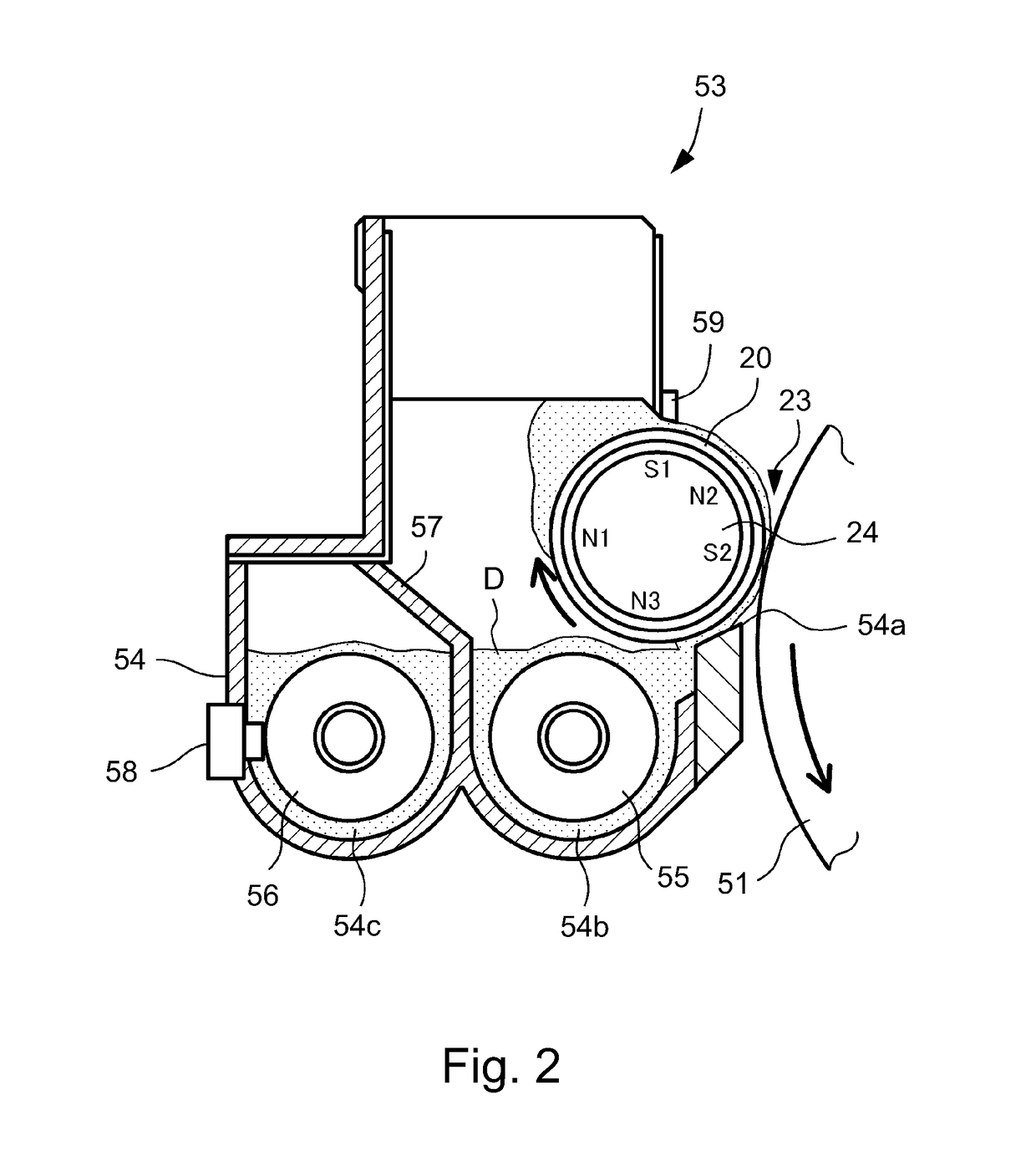
[0029]In the following, a developing device in First Embodiment of the present invention will be specifically described with reference to FIGS. 1 to 3. In this embodiment, the developing device is described based on the case where as an example of an image forming apparatus including the developing device, a full-color printer of a tandem type is used. However, the developing device of the present invention is not limited to the developing device for use with the image forming apparatus of the tandem type but may also be a developing device for use with an image forming apparatus of another type. Further, the developing device is not limited to the developing device for use with the full-color image forming apparatus, but may also be a developing device for use with an image forming apparatus for forming a monochromatic image or a mono-color image. Or, the developing device can be carried out in various uses, such as printers, various printing machines, copying machines, facsimile m...
embodiment 1
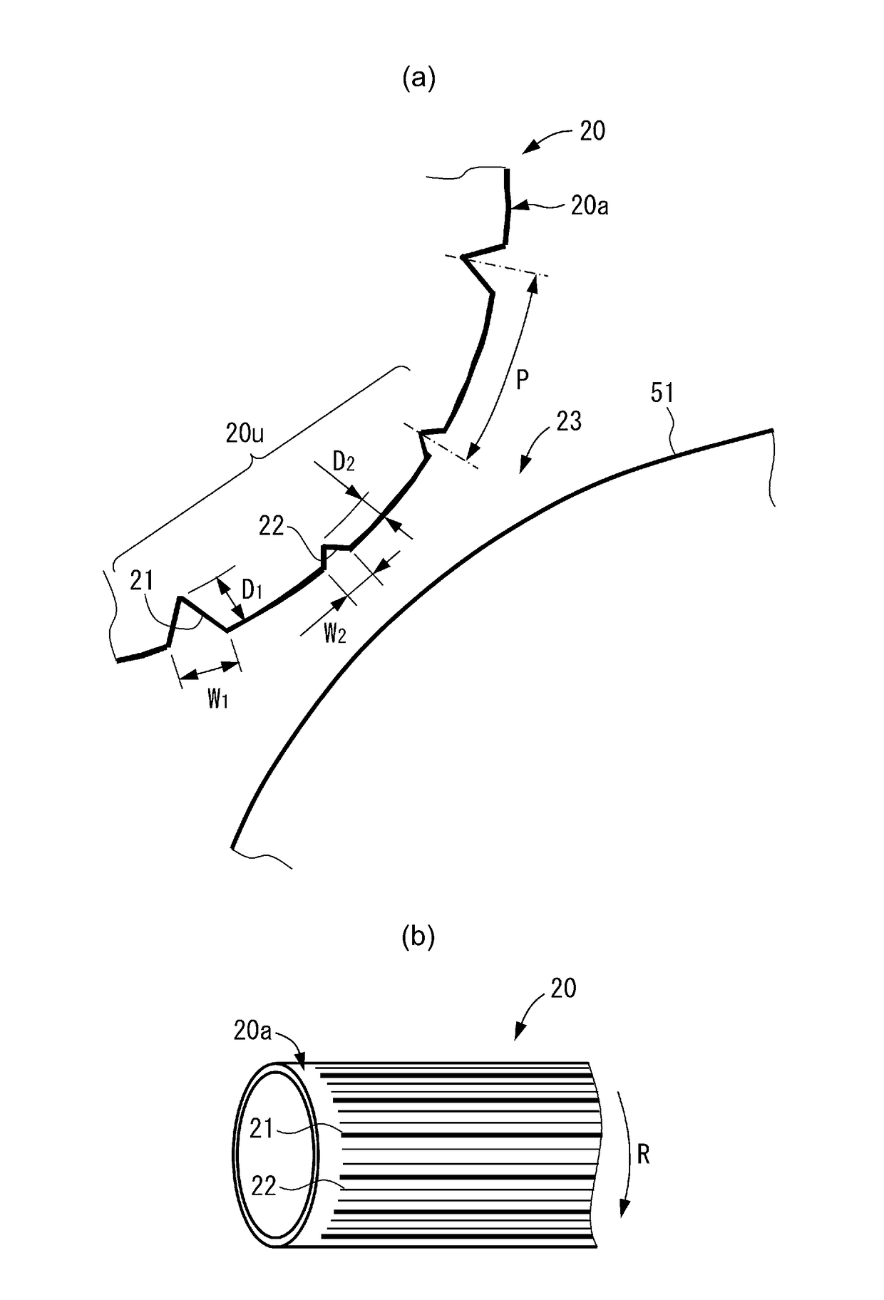
[0093]As shown in (a) of FIG. 5, the respective dimensions of the first grooves 21 and the second grooves 22 are as follows. The first grooves 21 were 50 (grooves) in number n1 of the grooves, 0.10 mm in opening width W1, 0.05 mm in depth D1 and 0.080 in groove ratio α1. The second grooves 22 were 100 (grooves) in number n2 of the grooves, 0.04 mm in opening width W2, 0.02 mm in depth D2 and 0.064 in groove ratio α2. In this case, the all groove ratio (α1+α2) was 0.144 and the groove pitch was 0.418 mm. As a result, the groove ratio CI of the first grooves 21 was 0.080 which was 0.1 or less, and therefore the SB was set at 0.35 mm which was not less than 0.3 mm. Further, the coated state was also stable. Further, the all groove ratio (α1+α2) was 0.144 which was not less than 0.1 and the groove pitch was 0.418 which was small, and therefore the density non-uniformity in groove pitch did not generate.
embodiment 2
[0094]As shown in (b) of FIG. 5, the respective dimensions of the first grooves 21 and the second grooves 22 are as follows. The first grooves 21 were 50 (grooves) in number n1 of the grooves, 0.10 mm in opening width W1, 0.05 mm in depth D1 and 0.080 in groove ratio α1. The second grooves 22 were 100 (grooves) in number n2 of the grooves, 0.03 mm in opening width W2, 0.04 mm in depth D2 and 0.048 in groove ratio α2. In this case, the all groove ratio (α1+α2) was 0.128 and the groove pitch was 0.418 mm. As a result, the SB and the stability of the coated state were good similarly as in Embodiment 1. Further, the coated state was also stable. Further, the all groove ratio (α1+α2) was 0.128 which was not less than 0.1 and the groove pitch P was 0.418 which was small, and therefore the density non-uniformity in groove pitch P did not generate.
PUM
 Abstract
Description
Claims
Application Information
 - R&D
- Intellectual Property
- Life Sciences
- Materials
- Tech Scout
- Unparalleled Data Quality
- Higher Quality Content
- 60% Fewer Hallucinations
Browse by: Latest US Patents, China's latest patents, Technical Efficacy Thesaurus, Application Domain, Technology Topic, Popular Technical Reports.
© 2025 PatSnap. All rights reserved.Legal|Privacy policy|Modern Slavery Act Transparency Statement|Sitemap|About US| Contact US: help@patsnap.com


