
Convertible pallet jack with rollers

a pallet jack and roller technology, applied in the direction of lifting devices, vehicle sub-unit features, transportation and packaging, etc., can solve the problems of inability to lift containers with standard pallet jacks, operator being forced to leave the pallet, damage to the pallet, etc., to facilitate the transfer of containers, facilitate the interchange, and slow the effect of moderate operation of the pallet jack

Inactive Publication Date: 2017-09-14
BURROW ROY C
View PDF0 Cites 0 Cited by
  • Summary
  • Abstract
  • Description
  • Claims
  • Application Information

AI Technical Summary

Benefits of technology

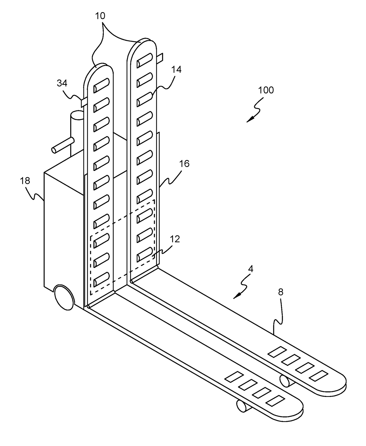
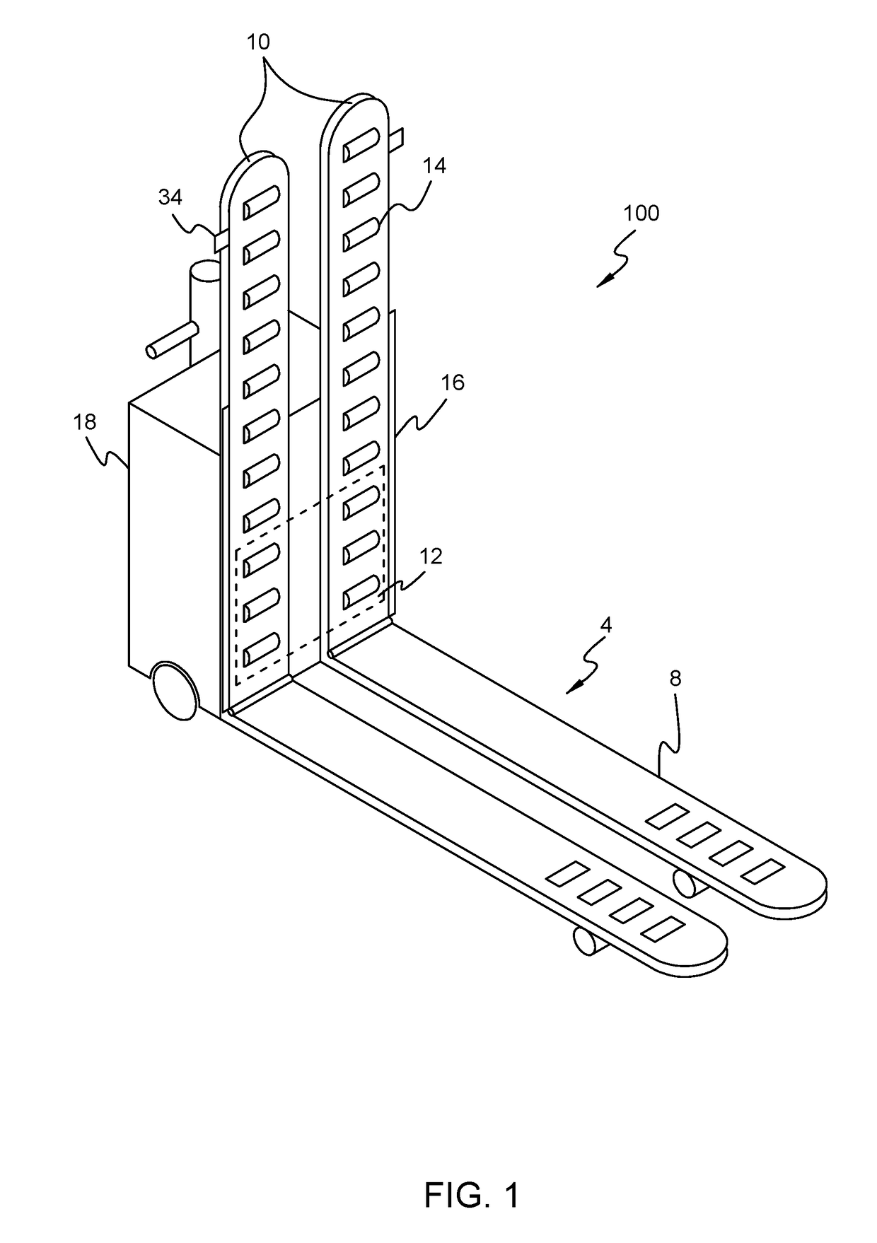
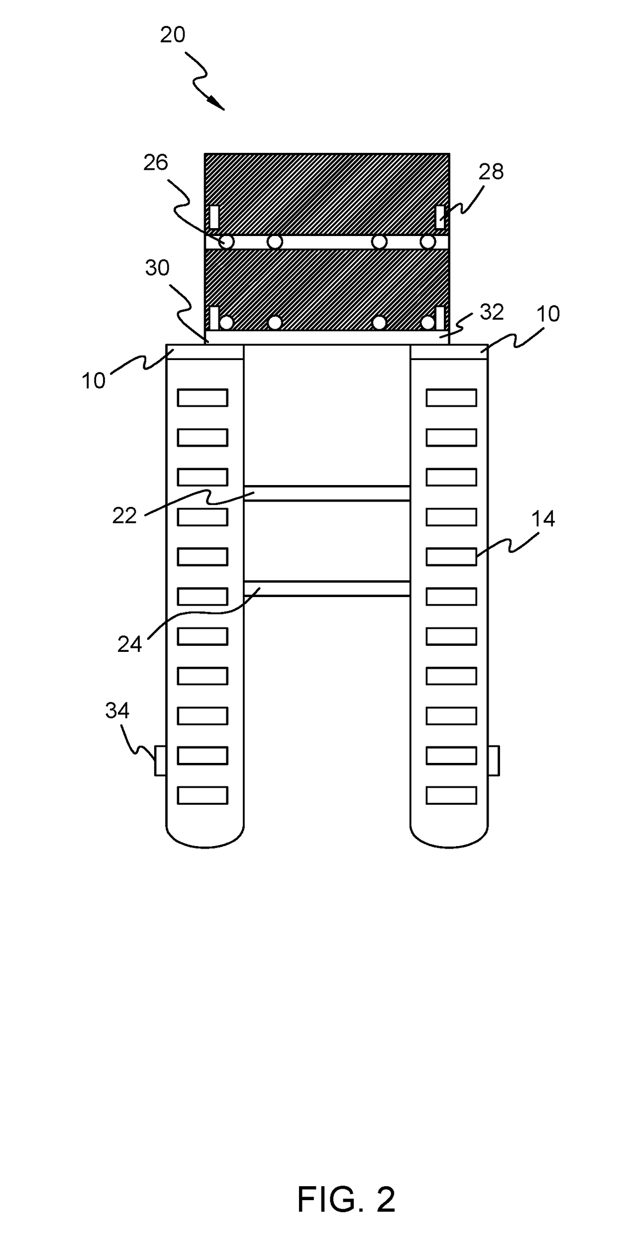
The present invention is a device that allows a container to be transferred from a floor onto a pallet jack without requiring a vertical lifting force or an external attachment to the container. The device uses an inclined ramp and the standard forward motion of the pallet jack to create a force on the container sufficient to lift it onto the forked support arms. The forked support arms have rollers embedded in them that allow the container to move into proper position on the pallet jack for transfer without needing additional force. The device can be used with a variety of containers and can be easily attached or detached from a standard pallet jack. The design of the device allows for slow to moderate operation of the pallet jack to achieve sufficient results. The device can be used with different types of materials and can be easily switched between a standard pallet jack and a pallet jack with embedded rollers. The rollers in the support arms span the entire length of the arms and the inclined ramp can be attached to existing components of the forked support arm to allow for unpalletized containers or non-standard pallets to be loaded.

Problems solved by technology

However, pallet openings are not always of standard size, thereby creating the potential for an operator to be forced to leave the pallet, or risk damaging the pallet by attempting to use incompatible support arms.
Further, a standard pallet jack is unable to lift containers that have no slots for a standard pallet jack.

Method used


Image

  • Convertible pallet jack with rollers
  • Convertible pallet jack with rollers
  • Convertible pallet jack with rollers

Examples


Embodiment Construction

[0022]At the outset, it should be clearly understood that like reference numerals are intended to identify the same structural elements, portions, or surfaces consistently throughout the several drawing figures, as may be further described or explained by the entire written specification of which this detailed description is an integral part. The drawings are intended to be read together with the specification and are to be construed as a portion of the entire “written description” of this invention as required by 35 U.S.C. §112. As used in the following description, the terms “horizontal”, “vertical”, “left”, “right”, “up”, “down”, as well as adjectival and adverbial derivatives thereof (e.g., “horizontally”, “vertically”, “upwardly”, etc.) simply refer to the orientation of the illustrated structure as the particular drawing figure faces the reader. Similarly, the terms “inwardly” and “outwardly” generally refer to the orientation of a surface relative to its axis of elongation, o...


PUM


Abstract

A pallet jack has a forked platform with rollers embedded in the arms of the fork. The rollers are located at intervals from the front of the arms to the rear. The rollers work in conjunction with an inclined ramp, also having embedded rollers, attached to the front of the arms to lift a container onto the forks. Once a container is aligned in front of the inclined ramp, the pallet jack is driven forward. The momentum of the pallet jack, at standard speed, causes the inclined ramp to insert underneath the container and lifts the container onto the arms. The rollers allow the container to move into position on the pallet jack for transfer. An overlay platform may cover the host forks for standard pallet transfer. The overlay platform may have embedded rollers and can be rotated into position over a standard fork.

Description

[0001]This application is a divisional of U.S. application Ser. No. 15 / 066,628, filed on Mar. 10, 2016. No new matter has been introduced.BACKGROUND[0002]The present disclosure relates to pallet jacks with hydraulic lift that may be used in industry for lifting and transporting loaded pallets and other containers and for unloading at new locations. Transporting containers in an industrial setting is a process that has been refined and standardized over many years. Typically, pallets are designed to be compatible with standard pallet jacks to automate loading and unloading.[0003]In the art of material handling, pallets jacks typically include wheeled devices intended for the manual lifting of a pallet, with a load resting thereon, to transport the pallet and load from one work area to another. U.S. Pat. No. 4,589,669 discloses an exemplary pallet jack, or hydraulic pallet truck. Pallet jacks typically include forked support arms upon which extensible rollers are mounted at terminal e...

Claims


Application Information

Patent Timeline
Patent Type & Authority Applications(United States)
IPC IPC(8): B65G13/00B62B3/06
CPCB65G13/00B62B3/06B62B2203/74B62B2203/20B60Y2410/124B66F9/12B66F9/19
Inventor BURROW, ROY C.
Owner BURROW ROY C
Learn More