A garment care device for drying and sanitizing garments

Inactive Publication Date: 2017-09-14
KONINKLJIJKE PHILIPS NV
View PDF1 Cites 15 Cited by
  • Summary
  • Abstract
  • Description
  • Claims
  • Application Information

AI Technical Summary

Benefits of technology

[0011]The garment care device may comprise an ultraviolet lamp. The ultraviolet lamp is configured to shine ultraviolet rays into the chamber to sanitize the garments. Therefore, the time it takes for the garment care device to sanitize garments is reduced. The ultraviolet lamp may be a UV-C lamp.
[0012]In one embodiment, the garment care device comprises a first internal wall disposed between the air channel and the chamber, and the air inlet is formed through the first internal wall. This helps to save space and therefore make the garment care device more compact. In one embodiment, the garment care device comprises a second internal wall that is located proximate to an end of the first internal wall and the air outlet is configured to draw the air in the chamber along the second direction towards the second internal wall. The garment care device may comprise rear, side, top, bottom and/or door walls. The first internal wall may comprise one of the rear, side, top, bottom and/or door walls and the second internal wall may comprise another one of the rear, side, top, bottom and/or door walls. The first and se

Problems solved by technology

However, devices for hygienic sterilisation of garments are less common.
Conventional washing machines do not typically reach the temperatures required to effectively sanitise clothing, meaning bacteria may survive the washing process and continue to grow on the garments.
However such devices suffer the draw back that any remaining ozone residue may cause an environmental safety hazard if it escapes into the local envi

Method used


Image

  • A garment care device for drying and sanitizing garments
  • A garment care device for drying and sanitizing garments
  • A garment care device for drying and sanitizing garments

Examples


Example

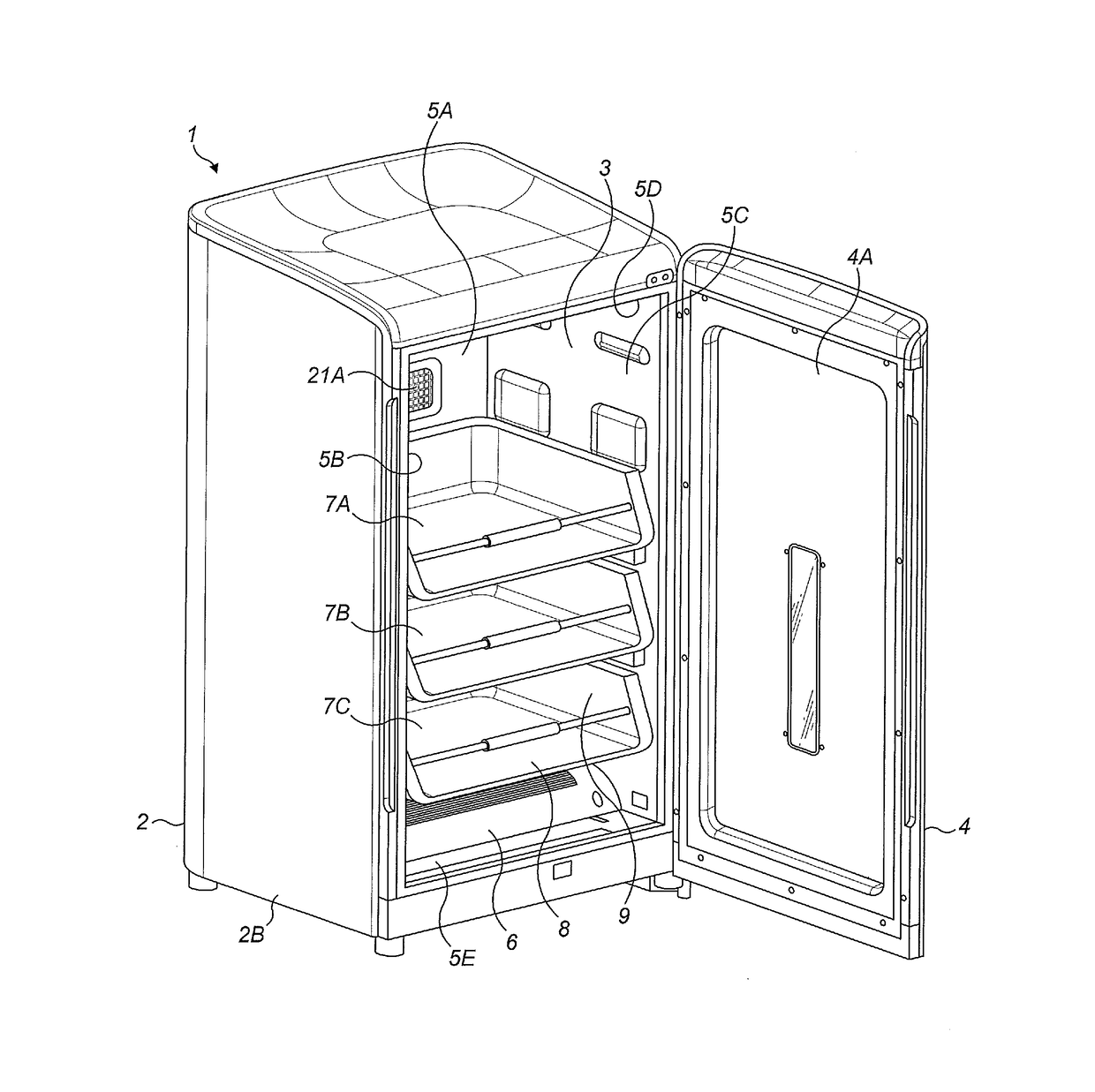
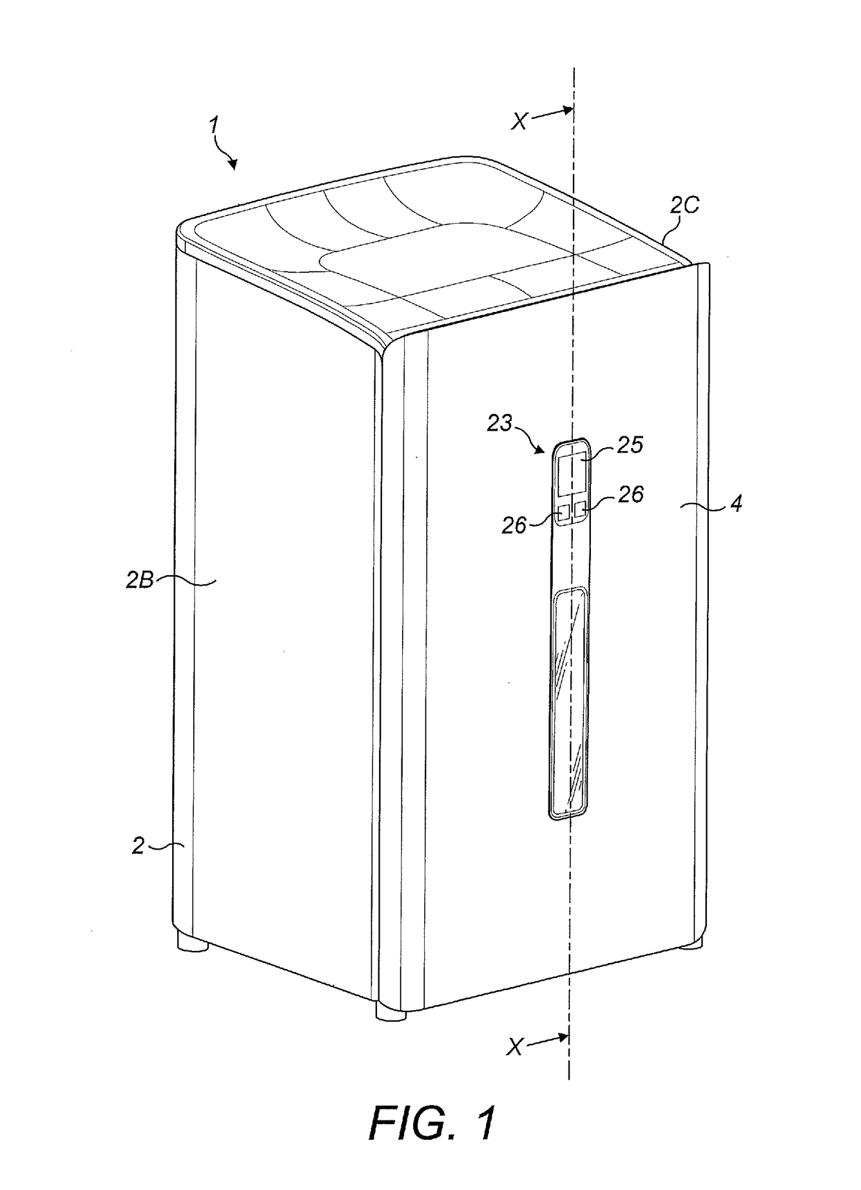
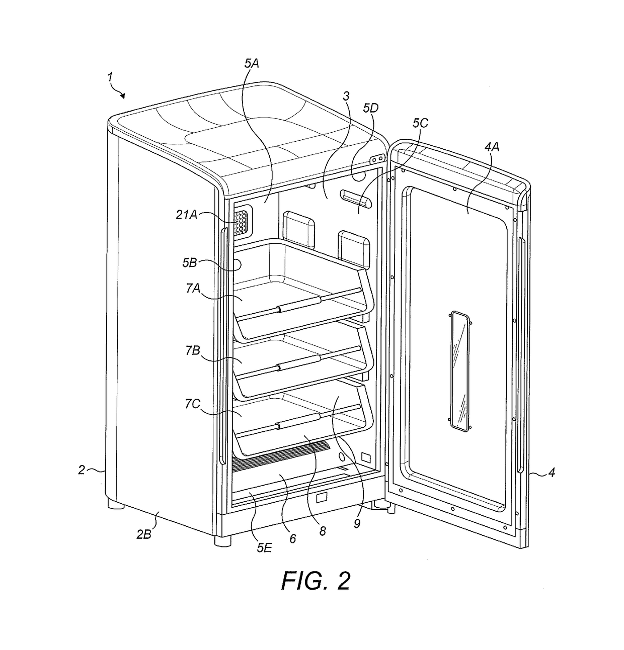
[0033]Referring to FIGS. 1 to 9, a garment care device 1 of an embodiment of the invention is shown. The garment care device 1 comprises a housing 2 with an opening 3. The garment steamer 1 further comprises a door 4 that is connected to the housing 2 via a hinge and can be opened allow a user to access the interior of the housing 2 via the opening 3.

[0034]The housing 2 comprises an exterior rear wall 2A and opposing exterior side walls 2B, 2C and the door 4 comprises a door wall 4A. The exterior rear and side walls 2A, 2B, 2C and the door wall 4A are generally planar such that when the door 4 is closed the garment care device 1 is generally parallelepiped in shape (as shown in FIG. 1).

[0035]FIGS. 3 and 4 show cross-sectional views of the garment care device 1 along the line X-X as shown in FIG. 1 and shows the garment care device 1 comprises a chamber 5 within the housing 2. The chamber 5 is generally rectangular prism shaped and is defined by an interior wall 5A (at the rear of ch...


PUM


Abstract

The present application relates to a garment care device (1) comprising a housing (2) and a chamber (5) within the housing (2) to receive at least one garment. The chamber (5) comprises an air inlet (17) and an air outlet (18). An air channel (15) links the air inlet (17) and the air outlet (18). The garment care device (1) further comprises a fan (19) for circulating an air flow between the chamber (5), the air outlet (18), the air channel (15) and the air inlet (17), and a heater (14) for heating the air flow. The air inlet (17) is configured such that air entering the chamber (5) flows along a first direction (A1, A2). The air outlet (18) is configured to draw the air in the chamber (5) along a second direction (B) transverse to the first direction (A1, A2).The garment care device further comprises a second fan (32) and an extraction channel (31) linking the chamber (5) with the second fan (32). The second fan (32) is configured to selectively draw an air flow out of the chamber (5) and into the extraction channel (31). The garment care device (1) allows improving the drying and sanitizing of garments.

Description

FIELD OF THE INVENTION[0001]The invention relates to the field of garment care devices.BACKGROUND OF THE INVENTION[0002]With the goal of maintaining a clean and hygienic domestic environment, various cleaning and sterilisation appliances are available. Such devices include sterilisers for grooming utensils, tooth brushes, cooking utensils and infant feeding equipment. However, devices for hygienic sterilisation of garments are less common.[0003]Conventional washing machines do not typically reach the temperatures required to effectively sanitise clothing, meaning bacteria may survive the washing process and continue to grow on the garments. There are commercially available sterilising washing machines that provide cold water with ozone. However such devices suffer the draw back that any remaining ozone residue may cause an environmental safety hazard if it escapes into the local environment. Washing machines are also available that provide a wash cycle capable of heating water up to...

Claims


Application Information

Patent Timeline
IPC IPC(8): D06F58/20A61L2/10D06F58/10
CPCD06F58/203D06F58/10A61L2202/26A61L2/10D06F58/20D06F2105/28D06F58/38D06F2103/08D06F2105/30D06F2103/32A61L2/00A61L9/00
Inventor GAO, PENGXIAO, TAIKANG
Owner KONINKLJIJKE PHILIPS NV
Why Eureka
Try Eureka