Desktop vaporizer

a vaporizer and desktop technology, applied in the field of compact cooking units, can solve the problems of releasing other contaminants, wasting resources, and releasing other contaminants, and achieve the effect of accurate control and temperature regulation, and rapid vaporization of substances

Inactive Publication Date: 2017-09-14
STULTZ DAVID
View PDF0 Cites 33 Cited by
  • Summary
  • Abstract
  • Description
  • Claims
  • Application Information

AI Technical Summary

Benefits of technology

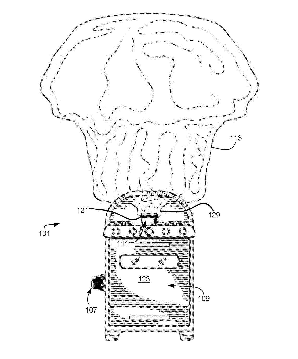
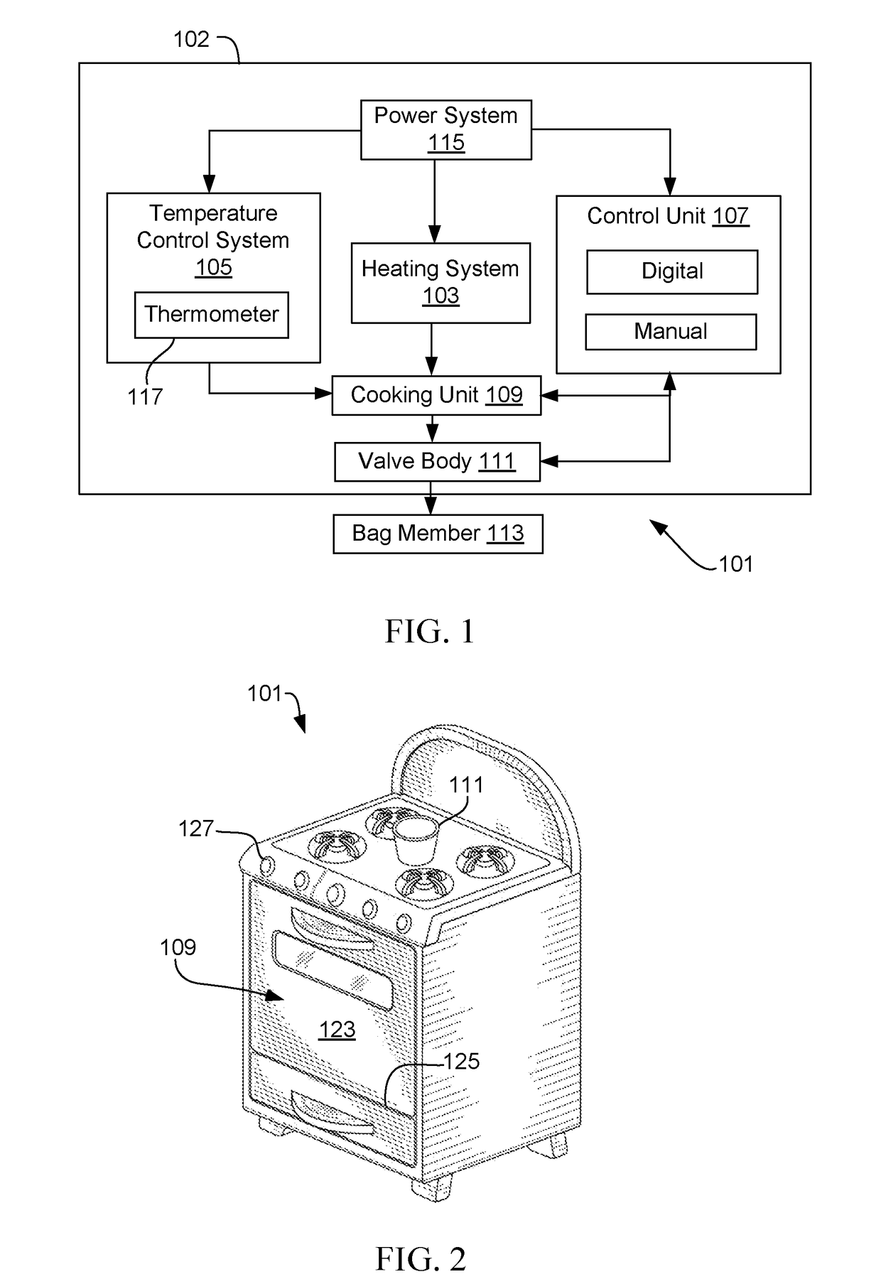
[0009]Operation of this device is configured to permit a user the ability to insert a desired amount of plant substance into the cooking unit and selectively control the duration and temperature at which the substances are heated. Vapor released through the heating process is passed through a valve bod and captured within an external bag member. A user is able to selectively remove the bad member for inhalation of the vapor.
[0010]The invention may take many embodiments but features the ability to more accurately control and regulate the temperature and heating systems to avoid escalating the level of heat to a level wherein the substance burns. Additionally, the vapor is externally captured outside of the cooking unit / vaporizer unit and is removable through a bag member wherein the user is able to wait to inhale after the temperature of the vapor has lowered. The external bag member also permits the user to more quickly vaporize substances by replacing the bag member with a replacement bag member for filling with vapor while the first bag member is consumed. In these ways, this system overcomes the disadvantages inherent in existing methods and system described above.

Problems solved by technology

A disadvantage of this process is the harmful byproducts remaining in the vapor through burning the substance.
This same disadvantage is likewise seen with other substances that are burned or inhaled in vapor form.
As stated above, a common disadvantage of many systems is that the plant substances are actually burned, thereby releasing other contaminants.
Additionally, systems tend to require a user to inhale the vapor during the burning or shortly thereafter wherein the vapor emitted is still hot and can burn the user.
Furthermore, often there is a lack of control of the precise temperature at which the plant substance is exposed.

Method used


Image

  • Desktop vaporizer
  • Desktop vaporizer
  • Desktop vaporizer

Examples


Embodiment Construction

[0023]Illustrative embodiments of the preferred embodiment are described below. In the interest of clarity, not all features of an actual implementation are described in this specification. It will of course be appreciated that in the development of any such actual embodiment, numerous implementation-specific decisions must be made to achieve the developer's specific goals, such as compliance with system-related and business-related constraints, which will vary from one implementation to another. Moreover, it will be appreciated that such a development effort might be complex and time-consuming but would nevertheless be a routine undertaking for those of ordinary skill in the art having the benefit of this disclosure.

[0024]In the specification, reference may be made to the spatial relationships between various components and to the spatial orientation of various aspects of components as the system and devices are depicted in the attached drawings. However, as will be recognized by t...


PUM


Abstract

A system and method for the production and capturing of clean vapors from the vaporizing of a plant substance is described. The system includes a heating system configured to generate heat within a cooking unit. A temperature control system is configured to monitor the level of heat generated by the heating system. Both systems are regulated by a control unit. The control unit is configured to provide an interface for a user to regulate the performance of the temperature control system and the heating system. The cooking unit defines a fully enclosed volume to contain the heat generated. A valve body is in communication with the cooking unit and configured to regulate the release of gases within the cooking unit as it passes into a bag member. The bag member is used to capture released vapor generated by vaporizing the plant substance.

Description

CLAIM OF PRIORITY[0001]This application claims the benefit of U.S. Design application Ser. No. 29 / 557,830, filed 11 Mar. 2016. The information contained therein is hereby incorporated by reference.BACKGROUND[0002]1. Field of the Invention[0003]The present application relates to a compact cooking unit, and more particularly to a device used to vaporize a substance and capture the vapor therein.[0004]2. Description of Related Art[0005]Various plant substances are commonly used to provide recreational and medicinal health benefits. One typical way of administering the plant substance is through inhalation after the substance has been heated. This process involves heating the substance until it burns and in turn releases a vapor remnant. The vapor remnant is then inhaled by the user for his / her elected purpose. This is process is performed daily through cigarettes, where tobacco is burned and then inhaled. A disadvantage of this process is the harmful byproducts remaining in the vapor t...

Claims


Application Information

Patent Timeline
Patent Type & Authority Applications(United States)
IPC IPC(8): F22B3/02A24F47/00A61M15/00A61M16/00A61M16/10A61M16/20A24F40/20A24F40/485A24F40/53A24F40/60
CPCF22B3/02A61M16/109A61M16/20A61M15/0086A61M2205/502A24F47/004A61M2205/3368A61M2205/59A61M16/0078F22B1/28A61M11/041A61M2205/36A24F40/53A24F40/60A24F40/485A24F40/20
Inventor STULTZ, DAVID
Owner STULTZ DAVID
Why Eureka
Try Eureka