
Method for operating a heat exchanger system and heat exchanger system

Active Publication Date: 2017-09-14
GUNTNER
View PDF7 Cites 3 Cited by
  • Summary
  • Abstract
  • Description
  • Claims
  • Application Information

AI Technical Summary

Benefits of technology

The present invention provides a method and system for operating a heat exchange system that is simple, inexpensive and easy to adjust, service, and analyze remotely. This allows for quick and simple adjustments and servicing even when no corresponding technical devices are available, such as during an emergency or at an airport. This method also eliminates the need for expensive and complex recruiting of service technicians. Overall, this improves the overall performance and reduces costs of heat exchange systems.

Problems solved by technology

It is a disadvantage of this method and of the heat exchange system that one or more desired values have to be adjusted at the control unit prior to the putting into operation of the heat exchange system and a change of a desired value has to be carried out directly at the control unit by a technician or engineer.
The adjustment of one or more desired values or the reading out of one or more actual values is equally satisfied in a very disadvantageous, complex and / or expensive manner.
For this purpose, either corresponding hardware or a display, which enables a display or an input of an actual value, has to be attached to the heat exchange system or the heat exchange system, in particular the control unit, has to be wired in a very complex and / or expensive manner to a building services management system at the location of installation.
After the installation and the putting into operation, changes of the adjustment of a desired value, of an operating mode or of a function but also the reading off / reading out of an actual value or the carrying out of remote servicing are, frequently for construction reasons alone, awkward and thus complex and / or expensive using the known methods and known heat exchange systems, for example because the heat exchange system is not easily directly accessible in the installed state.
The opening of the housings is in this respect not only complex and / or expensive and awkward, but even impossible in part.
The heat exchange systems then, for example, have to be taken out of operation since an opening of the housing of the heat exchange system is otherwise not allowed for safety reasons alone or is not possible at all in the operating state for technical reasons.
A technical expert is not always available.
The service personnel, for example a technician or a graduate engineer, is underway in many cases and cannot be on site quickly to service the heat exchange system of a client.
However, in the case of an emergency, a fast response is necessary which is not possible with the known installations.
Personnel therefore frequently have to be recruited on site in a very complex and / or expensive manner and at more expensive terms.
In a first operating mode, a desired condensing value cannot be achieved due to a high environmental temperature and the heat exchanger can be operated in a full load operation.
This was not possible in this way with the previous heat exchange systems.

Method used


Image

  • Method for operating a heat exchanger system and heat exchanger system
  • Method for operating a heat exchanger system and heat exchanger system
  • Method for operating a heat exchanger system and heat exchanger system

Examples


Embodiment Construction

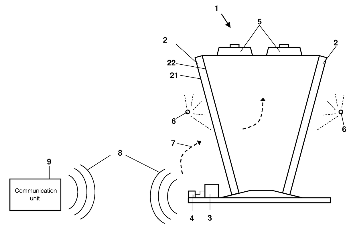
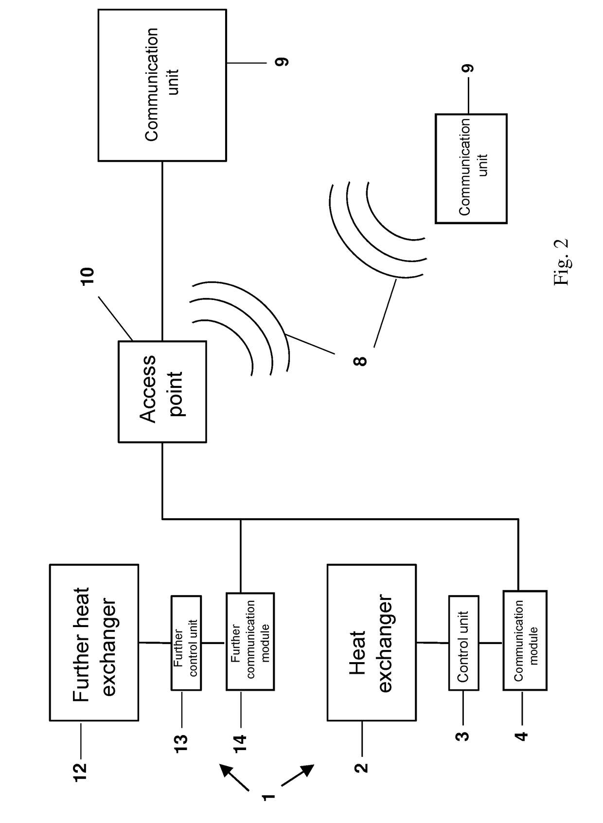
[0073]FIG. 1 shows a schematic representation of a first embodiment of a heat exchange system 1 in accordance with the invention. The heat exchange system 1 comprises a heat exchanger 2, wherein an outer boundary of the heat exchanger 2 is formed by an inflow surface 21 and by an outflow surface 22 such that, in the operating state, for the exchange of heat between a transport fluid and a heat transfer fluid flowing through the heat exchanger 2, the transport fluid can be supplied to the heat exchanger 2 over the inflow surface 21, can be brought into flow contact with the heat exchanger 2 and the transport fluid can be led off again out of the heat exchanger 2 over the outflow surface 22. The heat exchange system 1 additionally comprises a fan 5 which is configured and arranged such that the transport fluid can be transported through the heat exchanger 2 over the inflow surface 21 to the outflow surface 22 and a control unit 3, in particular a control unit 3 having a data processin...


PUM


Abstract

A method of operating a heat exchange system includes a heat exchanger including an outer boundary formed by inflow and outflow surfaces, a fan configured and arranged such that a transport fluid is transported through the heat exchanger over the inflow surface to the outflow surface and a control unit that receives one or more actual values from the heat exchanger and / or fan in the operating state and that one or more predetermined values of the heat exchanger and / or of the fan are adjusted by the control unit. The heat exchange system further includes a communication module in signal communication with the control unit, the communication module receiving one or more actual values from the control unit and / or one or more predetermined values transmitted from the communication module to the control unit, with the communication module being in signal communication with a communication unit at least at times.

Description

CROSS-REFERENCE TO RELATED APPLICATIONS[0001]This application is a U.S. National Stage application of International Application No. PCT / EP2015 / 071813, filed Sep. 23, 2015, which claims priority to EP Application No. 14188678.8, filed Oct. 13, 2014 the contents of each of which are hereby incorporated herein by reference.BACKGROUND[0002]Field of Invention[0003]The invention relates to a method of operating a heat exchange system and to a heat exchange system[0004]Background Information[0005]Methods of operating a heat exchange system and heat exchange systems are already known and can be found in a plurality of technical applications. Heat exchange systems are used in refrigeration plants such as in common domestic refrigerators; in air-conditioning systems for buildings or in vehicles of all kinds, above all in motor vehicles, in aircraft and in ships; as water coolers or as oil coolers in combustion engines; as condensers or as evaporators in refrigerant circuits; and in further in...

Claims


Application Information

Patent Timeline
IPC IPC(8): F28F27/00F28D3/00
CPCF28D3/00F28F27/00F28B11/00F24F11/56
Inventor KOCHER, JORGZIEGLTRUM, ULRICH
Owner GUNTNER
Learn More