Method for identifying friction parameter for linear module

a technology of friction parameters and linear modules, applied in the field of linear systems, can solve the problems of difficult identification, large limitation of known approaches, and inability to meet the requirements of tightening, and achieve the effect of facilitating the parameter identification process and making it much more feasible in practi

Inactive Publication Date: 2017-09-14
HIWIN TECH
View PDF2 Cites 5 Cited by
  • Summary
  • Abstract
  • Description
  • Claims
  • Application Information

AI Technical Summary

Benefits of technology

[0006]The primary objective of the present invention is to provide a method for identifying friction parameters for a linear module, which eliminate

Problems solved by technology

However, such preload inevitably increases friction between the contacting surfaces, and leads to quadrant errors when the screw shaft changes directions at a high speed, thereby affecting adversely the accuracy of the automated equipment.
However, the use of the LuGre friction mod

Method used


Image

  • Method for identifying friction parameter for linear module
  • Method for identifying friction parameter for linear module
  • Method for identifying friction parameter for linear module

Examples


Embodiment Construction

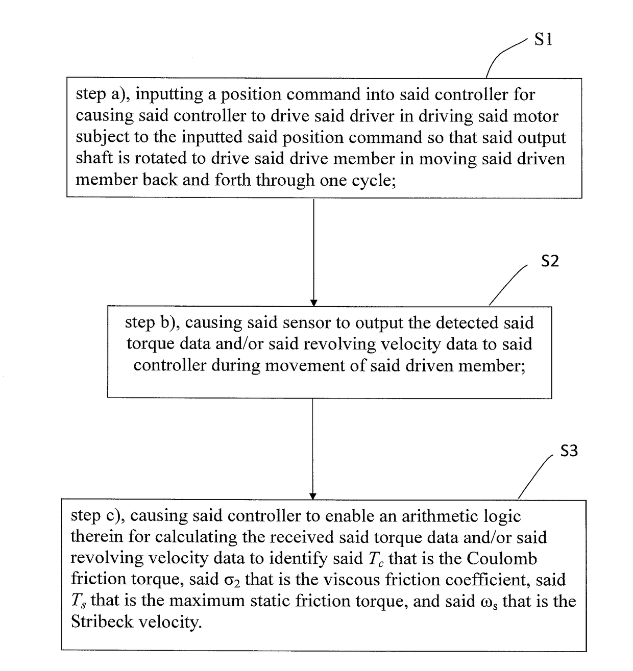
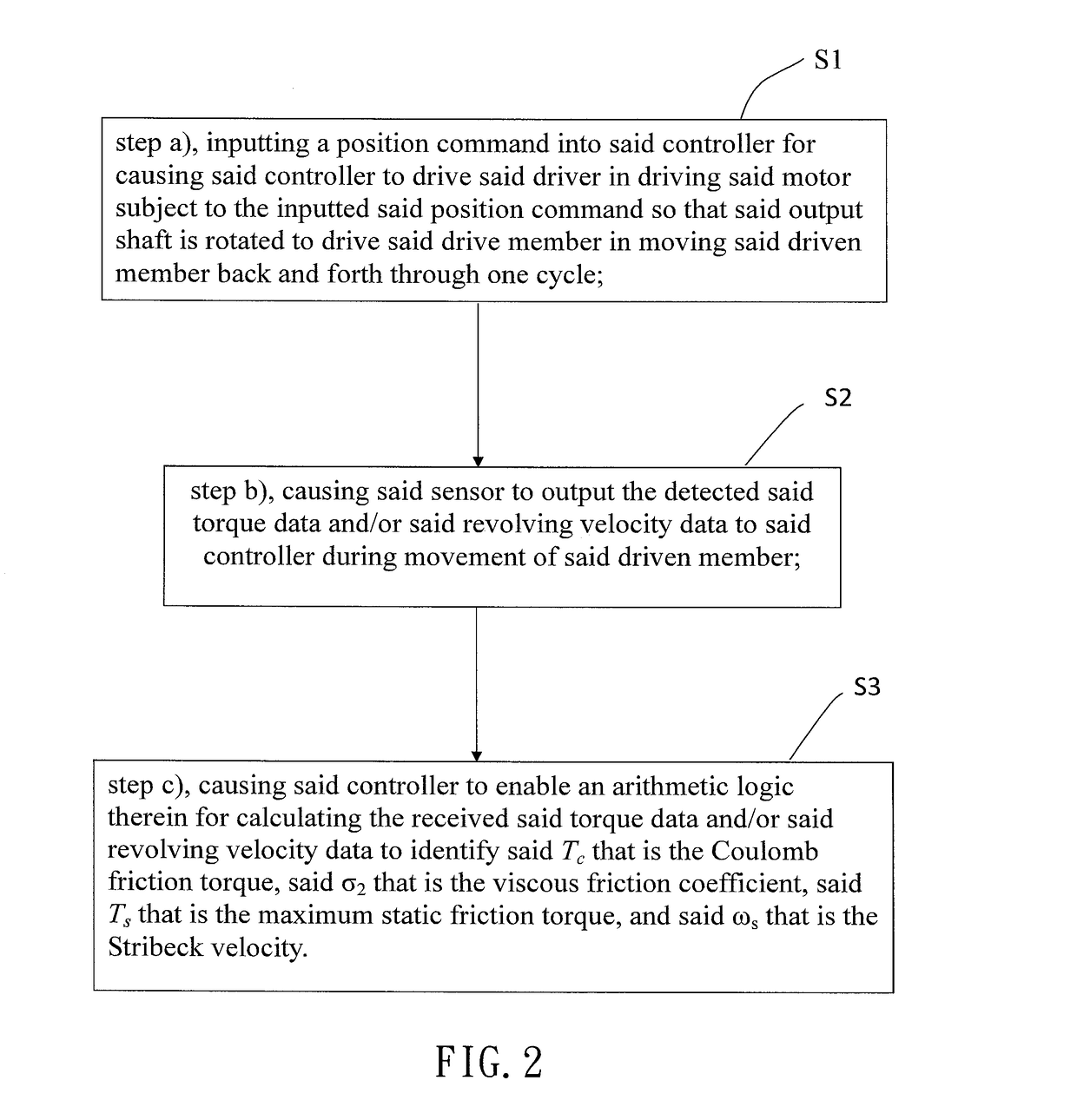
[0016]Referring to FIG. 1, according to the present invention, a method for identifying friction parameters for a linear module comprises a step a) S1, a step b) S2, and a step c) S3. In LuGre friction model, the friction parameters to be identified are Tc that is the Coulomb friction torque, σ2 that is the viscous friction coefficient, Ts that is the maximum static friction torque, and ωs that is Stribeck velocity.

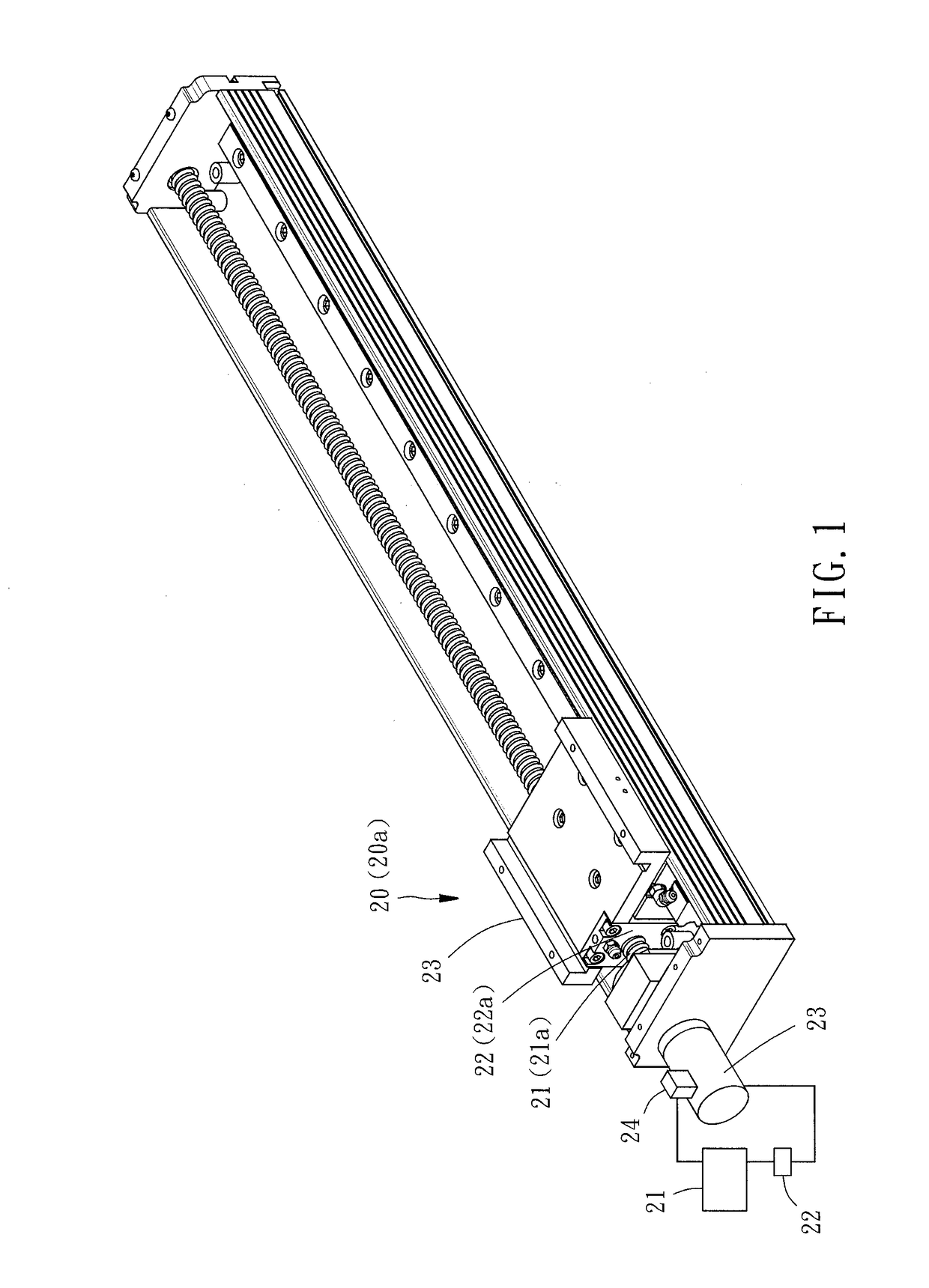
[0017]It is to be noted that, in the present preferred embodiment, the identification method is used in a linear module 10. The linear module 10 is driven by a drive module 20. The drive module 20 comprises a controller 21, a driver 22, a motor 23 with an output shaft (not shown), and a sensor 24. The controller 21 has the function of storing, computing and outputting data, and can receive a position command or a speed command and convert the received position command or said speed command into a driving signal. The driver 22 is electrically connected to the controller 21...


PUM


Abstract

A method for identifying friction parameters for a linear module is disclosed. Since an acting interval of a friction is determined by a relative velocity between two contacting surfaces, and when the relative velocity is much greater than a Stribeck velocity, there is only a Coulomb friction and a viscous friction exist between the contacting surfaces, it is possible to use a measured torque signal of this interval to identify a Coulomb friction torque, a the linear module's friction torque, and the linear module's equivalent inertia. When the relative velocity between the two contacting surfaces is smaller than the Stribeck velocity, it is possible to identify a maximum static friction torque and the Stribeck velocity by referring to the three known parameters. Thereby, all the friction parameters can be identified within one reciprocating movement of the linear module, making the method highly feasible in practice.

Description

BACKGROUND OF THE INVENTION[0001]Technical Field[0002]The present invention relates to linear systems, and more particularly to a method for identifying friction parameters for linear module.[0003]2. Description of Related Art[0004]For automated equipment using ball screws, the automated equipment's accuracy of positioning mainly relies on the ball screw's preload that eliminates backlash in the ball screw and increase the rigidity of the ball screw. However, such preload inevitably increases friction between the contacting surfaces, and leads to quadrant errors when the screw shaft changes directions at a high speed, thereby affecting adversely the accuracy of the automated equipment.[0005]For addressing this issue, a known approach involves using a LuGre friction model to build up a relation curve between the friction torque and the velocity, and then identifying the relevant parameters by means of curve fitting. However, the use of the LuGre friction model requires many times of ...

Claims


Application Information

Patent Timeline
IPC IPC(8): G01P3/06G05B17/02G01L5/24
CPCG01P3/06G05B17/02G01L5/24G05B19/404G05B2219/41154G05B2219/42155
Inventor TSAI, MENG-SHIUNYUAN, WEI-HSIANGWANG, CHIH-WEIHUANG, HONG-WEILIU, CHUNG-CHING
Owner HIWIN TECH
Why Eureka
Try Eureka