
High speed gamma imaging device

a gamma radiation imaging and high-speed technology, applied in the field of gamma radiation imaging devices, can solve the problems of high resolution, low detection efficiency, and high cost of collimators, and achieve the effects of reducing the overlap of the detection lobe of the sensor, reducing the influence of overlaying between neighboring lobes, and reducing the overlapping of the sensor

Active Publication Date: 2017-09-14
INVAP SE
View PDF7 Cites 19 Cited by
  • Summary
  • Abstract
  • Description
  • Claims
  • Application Information

AI Technical Summary

Benefits of technology

The present invention proposes a device to face the challenges of gamma imaging with high efficiency and speed. The device consists of an array of neighboring sensors, each with a specific detection lobe that efficiently and quickly detects the incident gamma radiation. A geometric composition of the overlapping of the detection lobes creates the field of view of the gamma camera. The device uses a system of small-thickness side screens to reduce the overlapping of sensor's detection lobe with nearby lobes and minimize its influence on the detection lobe of the sensor itself. The device can detect low levels of radiation and provide a quick, efficient, and homogeneous response within the entire field of emission where the gamma field is created. It can be used as a large-size detector and is suitable for both fixed and mobile equipment, including aerial or ground vehicles.

Problems solved by technology

In these cameras, said resolution is high, but the detection efficiency is low because by using collimators the image is created at the expense of removing the detection of gamma radiation not aligned with the focal point, which it does that for a variety of applications the typical measurement time can be up to 10 minutes, and even more, to obtain a single complete gamma image.
Since collimators can be expensive and bulky for a variety of applications, improvements have been proposed, such as the so-called coded aperture collimators, which reduce the size of the collimator and, in turn, increase spatial resolution of the image of the gamma field.
13. This type of sensor has the disadvantage that the detection efficiency will be comparatively lower because it relies on simultaneous measurement of two gam
Although there are gamma sensor with high spatial resolution, based on the foregoing it is finally clear that general purpose gamma cameras will be slow to acquire an image in the open field, due to the low efficiency involved, and the fact that the images are blurry because the focus mechanisms used have low precision.
This has been a restriction for their current use, since the equipment available are expensive, bulky and heavy, and with inconvenient features and pricing for a large number of applications.
Although this type of gamma detector is fast and efficient, it does not generate an image of the gamma radiation from a given field of view; instead of being a kind of gamma camera, it is a detector, by quadrants, of the measurement of the anisotropy of the gamma field.
To acquire gamma images from extensive sources in open spaces, the high resolution of these sensors, given the number of pixels or two-dimensional elements available to compose an image is unnecessarily high, because, due to the properties of the gamma field, changes in spatial and angular components of the actual gamma field are very small, and the image is finally very blurry, regardless of whether it is acquired with high resolution of the gamma sensor.
That is why there are some detectors available which are extremely slow but relatively small and low-cost, not always included in the classical literature of gamma cameras.
But then problem remains that the shortest measurement time requires a greater height at the expense of losing spatial resolution of the gamma image or map.
Since these applications are most useful when the measurement is faster, this type of detectors present many limitations when used.
The gamma cameras mentioned above cannot be applied because the measurement time is too long for a moving vehicle, whether by air or land.
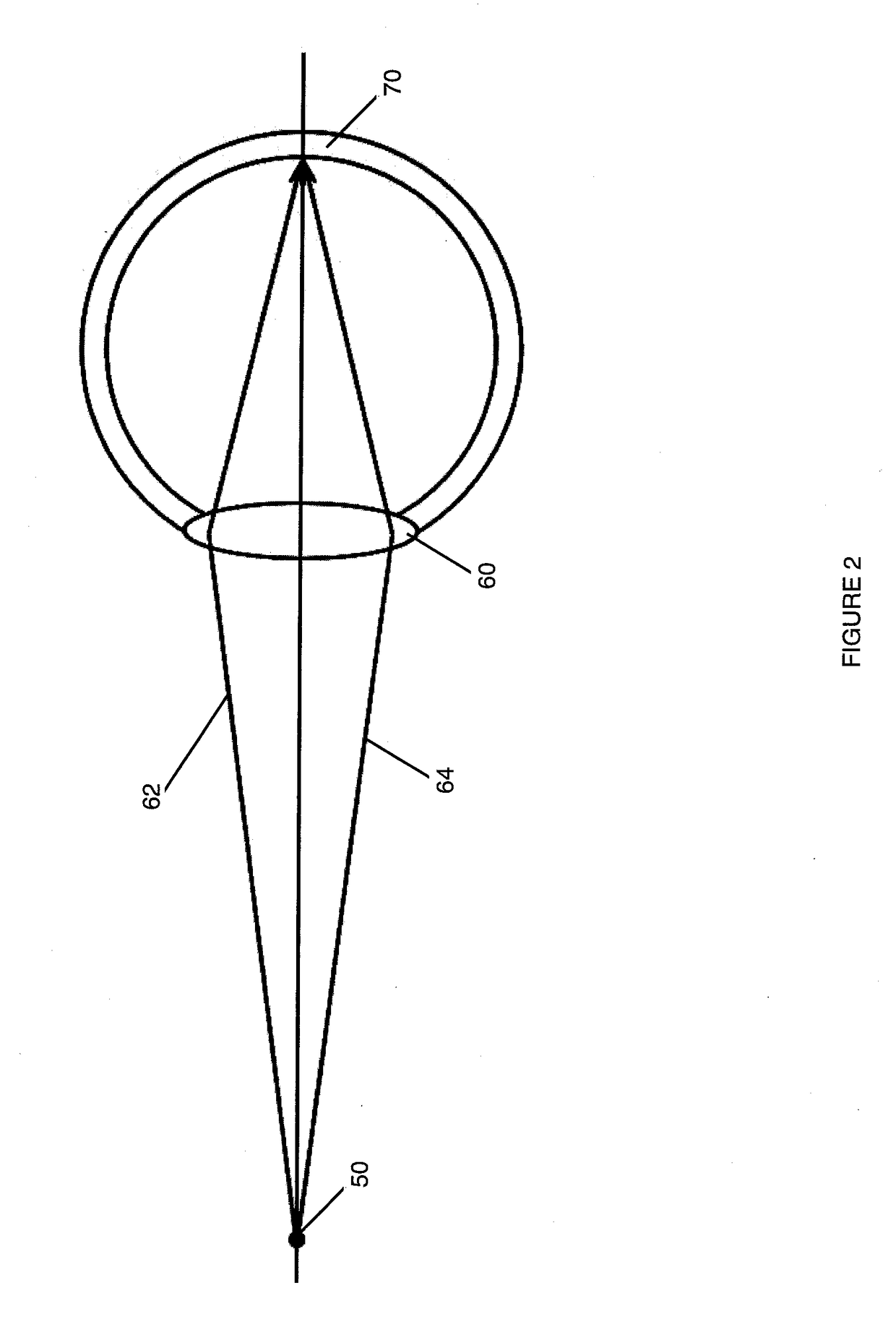
Due to this difference in interaction depending on whether it is a visible or gamma photon, the concept of inbound and outbound beam with its angle of incidence and output is lost, which means that there is no concept directly similar to the concept of lens and focus in terms of gamma radiation.

Method used


Image

  • High speed gamma imaging device
  • High speed gamma imaging device
  • High speed gamma imaging device

Examples


Embodiment Construction

[0052]Before proceeding to a detailed description, we can see that the creation described is not limited to the use as a detector type for a specific use, and that although the present description is shown and described as applied as a radiation monitor for fixed positions, it can be implemented in a variety of applications and sizes in different geometries and mechanical solutions, using different types of gamma detectors, for fixed or mobile applications, in order to create images of the gamma field.

[0053]The present invention presents a device capable of obtaining gamma images with high efficiency and within short periods of time, with a concept for the creation of the gamma image that can adapted to the sensitivity, speed and resolution needs of various uses. It applies a concept that is compatible with the intrinsic physical properties of the fields of gamma photons and the need to create an image at very high speed.

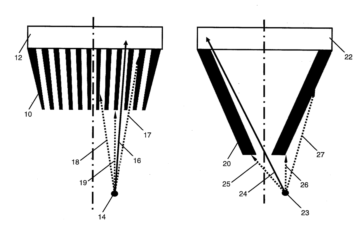
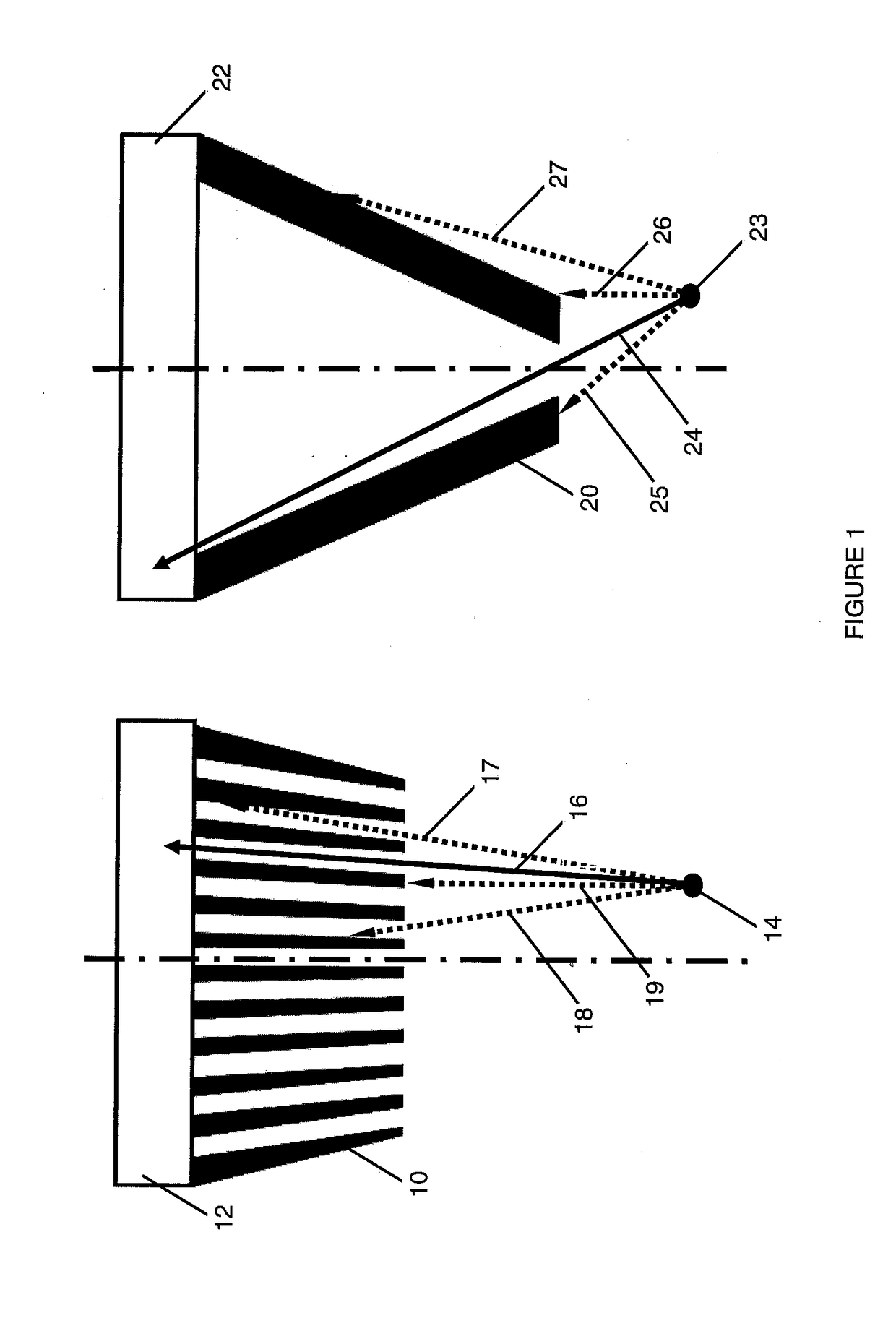
[0054]FIG. 1 is a simplified diagram of the two classical gamm...


PUM


Abstract

This invention presents a new device to produce images of the gamma field, specially designed for circumstances requiring high efficiency and fast response imaging, by applying the concept of image extraction within a given field of view, through the combination of efficient gamma radiation detectors. Each detector is located inside a shielding, with an area of the detector with no shielding to enter the incident gamma radiation detector with a plurality of angles in relation to the normal outgoing central axis to the surface of the detector through the unshielded area, where that central axis is divergent in relation to the outgoing central axes of neighboring detectors.

Description

CLAIM OF PRIORITY[0001]This application claims priority to Argentinian Patent Application No. AR P 2016 01 00612, dated Mar. 8, 2016, the entirety of which is incorporated herein by reference.FIELD OF THE INVENTION[0002]The main purpose of this invention submitted for an invention patent is a GAMMA RADIATION IMAGING DEVICE, especially designed for measurement under circumstances requiring imaging with high efficiency and response speed.[0003]More specifically, this invention consists of a gamma fields imaging device, through the concept of image acquisition within a given field of view, through the combination of efficient gamma radiation detectors, where each detector is located inside a compact collimator, with a detection lobe with known overlapping and with a central axis diverging in relation to the central axes of the neighboring detection lobes.BACKGROUND OF THE INVENTION[0004]Given a gamma radiation field coming from specific or extensive sources (fixed or mobile) located in...

Claims


Application Information

Patent Timeline
IPC IPC(8): G01T1/20
CPCG01T1/2018G01T1/1648G01T1/20187
Inventor FLORIDO, PABLONASSIF, EDUARDOARGÜELLES, MANUELFERNANDEZ BALDIS, FEDERICO
Owner INVAP SE
Learn More