Bronze colored heat treatable coated article having low solar factor value

a technology of solar factor value and heat treatment coating, which is applied in the direction of vacuum evaporation coating, door/window protective devices, units with parallel planes, etc., can solve the problems of inability to achieve such coloration, and inability to achieve coloration, so as to achieve good thermal stability and improve color control and/or range. , the effect of improving the color control

Active Publication Date: 2017-09-21
GUARDIAN GLASS LLC +1
View PDF9 Cites 8 Cited by
  • Summary
  • Abstract
  • Description
  • Claims
  • Application Information

AI Technical Summary

Benefits of technology

[0014]In certain example embodiments of this invention, heat treated (HT) coated articles have a glass side reflective ΔE* value due to heat treatment (e.g., thermal tempering) of no greater than 4.5, more preferably no greater than 4.0, even more preferably no greater than 3.5, and most preferably no greater than 3.0. For purposes of example, the heat treatment (HT) may be for at least about 5 minutes at a temperature(s) of at least about 580 degrees C., and is sufficient for thermal tempering. The term ΔE* is known in the art and is indicative of thermal stability upon heat treatment, and is defined and explained for example in U.S. Pat. No. 6,926,967 which is incorporated herein by reference.

Problems solved by technology

Unfortunately, while such layer stacks with NiCr IR reflecting layers provide efficient solar control and are overall good coatings, they are lacking in terms of being able to achieve a wider palette of available colors when desired combined with desirable solar control features.
For example, with such a coating stack, if bronze glass side reflective coloration is desired, it was not possible to achieve such coloration in combination with desirable solar control features and / or durability.
While low SF values are sometimes desirable for coated articles such as IG window units, the achievement of lower SF values may come at the expense of sacrificing coloration.
It is often desirable, but difficult, to achieve a combination of acceptable visible transmission, desirable glass side reflective coloration, and a low SF value for a coated article such as an IG window unit or the like.
However, these examples have undesirable green glass side reflective coloration.
Unfortunately, Examples 2 and 5 in US '899, while having desirable bronze coloration, suffer from undesirably high solar control features SF and SHGC.
Thus, the coatings of US '395 could not achieve desirable bronze glass side / external reflective coloration in combination with desirable solar control features and acceptable glass side / external / out reflectivity.

Method used


Image

  • Bronze colored heat treatable coated article having low solar factor value
  • Bronze colored heat treatable coated article having low solar factor value
  • Bronze colored heat treatable coated article having low solar factor value

Examples


examples

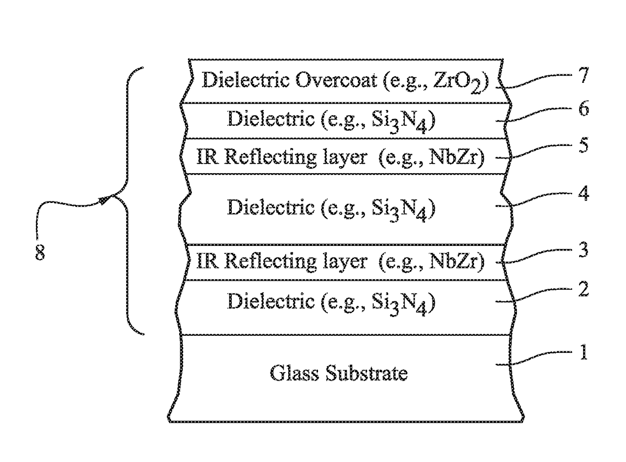
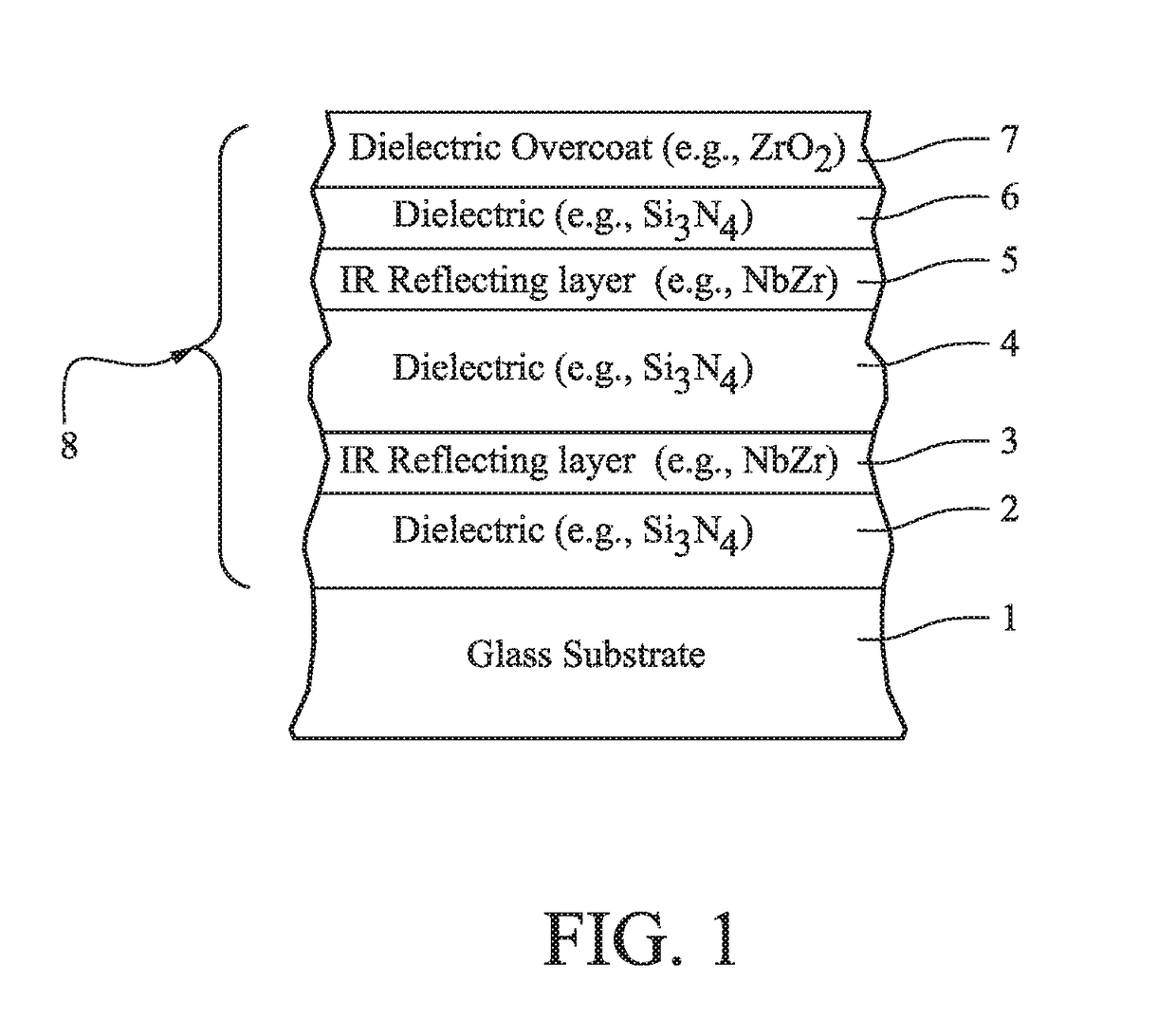
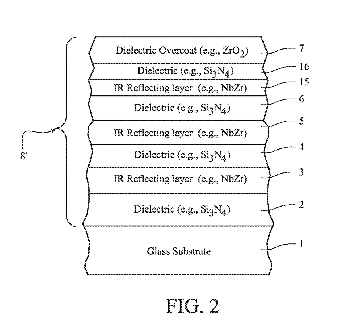
[0039]Example 1 was a layer stack on a clear glass substrate as shown in FIG. 1, and Example 2 was a layer stack on a clear glass substrate as shown in FIG. 2. Both were measured monolithically, heat treated and measured again. They were also put into IG window units as shown in FIG. 3. The silicon nitride layers in each example were deposited by sputtering a silicon target (doped with about 8% Al) in an atmosphere including argon and nitrogen gas. The glass substrates 1 and 30 were clear and 6 mm thick, and the air gap 34 in the IG window unit was 12 mm thick. The NbZr layers in each example were deposited by sputtering approximately 90 / 10 Nb / Zr magnetron sputtering targets in an atmosphere including argon and a small amount of nitrogen gas. Comparative Examples (CEs) 1-3 were provided for purposes of comparison. Layer thicknesses were in angstroms (Å).

TABLE 7Layer Stacks of ExamplesLayerEx. 1Ex. 2CE 1CE 2CE 3silicon nitride (layer 2):30Å30Å485Å600{acute over (Å)}1310ÅNbZr (layer 3...

example 3

[0048]Example 3 was similar to Example 1 with respect to the layer stack, as shown in FIG. 1. Example 3 was as follows: glass(5.8 mm clear) / Si3Nx(10 nm) / NbZr(7.2 nm) / Si3Nx(53.1 nm) / NbZr(9.4 nm) / Si3Nx(28 nm) / ZrOx(6.6 nm). Example 3 has SF and SHGC values similar to Example 1 above, realized glass side reflective bronze color, and had the following optical characteristics as coated (prior to thermal tempering): TY 15.0%; a*T −0.5; b*T 0.0; RG / outY 11.0%; a*G 2.5; b*G 9.0; RF / interior 8.5%; a*F 3.0; and b*F 18.0. Example 3 following thermal tempering (heat treatment) had the following optical characteristics: TY 14.0%; a*T −0.5; b*T 0.5; RG / outY 10.5%; a*G 2.5; b*G 8.5; RF / interior 10.0%; a*F 3.0; and b*F 18.0.

[0049]It is noted above that one, two or all of IR reflecting layers 3, 5, 15 may be of or include NiCrMo and / or NiCrMoNx in certain example embodiments of this invention. In such embodiments one, two or all of the IR reflecting layers 3, 5, 15 may, for example, be of or include ...


PUM

PropertyMeasurementUnit
visible reflectanceaaaaaaaaaa
SHGCaaaaaaaaaa
SHGCaaaaaaaaaa

Abstract

There are provided coated articles that include two or more infrared (IR) reflecting layers (e.g., of or including NbZr, Nb, NiCr, NiCrMo, and / or a nitride thereof) sandwiched between at least dielectric layers, and / or a method of making the same. The coating may be designed so that the coated articles realize bronze glass side reflective coloration in combination with a low solar factor (SF) and / or a low solar heat gain coefficient (SHGC). Such coated articles may be used in the context of monolithic windows, insulating glass (IG) window units, laminated windows, and / or other suitable applications, and may optionally be heat treated (e.g., thermally tempered) in certain instances.

Description

[0001]This application claims priority on U.S. Provisional Application 62 / 308,343, filed Mar. 15, 2016, which is incorporated herein by reference.[0002]This invention relates to coated articles that include two or more functional infrared (IR) reflecting layers sandwiched between at least dielectric layers, and / or a method of making the same. The coating may be designed so that the coated articles realize bronze glass side reflective coloration in combination with a low solar factor (SF) and / or low solar heat gain coefficient (SHGC). Such coated articles may be used in the context of monolithic windows, insulating glass (IG) window units, laminated windows, and / or other suitable applications, and may optionally be heat treated (e.g., thermally tempered) in certain instances.BACKGROUND AND SUMMARY OF THE INVENTION[0003]Solar control coatings having a layer stack of glass / Si3N4 / NiCr / Si3N4 are known in the art, where the metallic NiCr layer is the sole infrared (IR) reflecting layer in...

Claims


Application Information

Patent Timeline
Patent Type & Authority Applications(United States)
IPC IPC(8): C03C17/36E06B9/24E06B3/67C03C23/00C22C19/05
CPCC03C17/3681E06B2009/2464C03C17/3649C03C17/3626C22C19/055E06B3/6715E06B9/24C03C2218/156C03C2217/281C03C2217/27C03C2217/22C23C14/35C23C14/0652C23C14/083C23C14/18E06B2009/2417C03C23/007C03C17/36C03C17/3618C03C17/3639C03C17/366C03C17/3652
Inventor LINGLE, PHILIP J.DISTELDORF, BERND
Owner GUARDIAN GLASS LLC
Why Eureka
Try Eureka