Temporary Support and Raising Device

a technology of lifting device and supporting device, which is applied in the direction of lifting device, shaping building parts, props/chocks, etc., can solve the problems of high cost, large health and safety risks, and limited mechanical props,

Active Publication Date: 2017-09-28
MMC INNOVATIONS
View PDF3 Cites 12 Cited by
  • Summary
  • Abstract
  • Description
  • Claims
  • Application Information

AI Technical Summary

Benefits of technology

[0021]Preferably the movement means is contained between a support boss and an abutment means. Preferably the initial position of the support boss is adjustable. Preferably the initial position of the abutment means is adjustable. The abutment means may define the lower limit of extent for the movement means in a first direction and the support boss may set the upper limit of extent for the movement means in a second direction. Preferably the abutment means is fixed relative to the outer sleeve member. The support boss may be fixed relative to the inner core member. Accordingly, once both ends of the movement means are engaged respectively with the abutment means and the support boss, further movement of the movement means causes the inner core member to extend telescopically relative to the outer sleeve member.
[0033]Preferably the collar is threadably moveable along the threaded portion from an unsupporting position to a supporting position in order for the retraction prevention means to be activated to prevent the inner core member from being retracted into the outer sleeve member.
[0120]threadably moving the collar along the threaded portion from an unsupporting position to a supporting position in order for the retraction prevention means to be activated to prevent the inner core member from being retracted into the outer sleeve member.

Problems solved by technology

These mechanical props are limited, however, in terms of how much load may be lifted / supported and it is also well documented that there are considerable health and safety issues during the operation of raising / supporting such loads of varying weights and stresses.
The mining and civil engineering industries make use of elaborate, complex and intricate props which are very costly.
Whilst such props may be efficient and safe, they are not simple and quick and easy for use in more routine situations.
For example, such props are not very adaptable and they may be bespoke and designed with specific situations in mind.
Similarly, fire and rescue teams may encounter situations requiring a support, for example, to support a floor in danger of collapsing.
The emergency personnel will be working under strict time pressures and there may be limited space and visibility in which intricate and complicated operation may hinder the operation.
Furthermore, these situations are inherently likely to be risky and any equipment and apparatus would need to be safe and to not pose any explosive risk.

Method used


Image

  • Temporary Support and Raising Device
  • Temporary Support and Raising Device
  • Temporary Support and Raising Device

Examples


Embodiment Construction

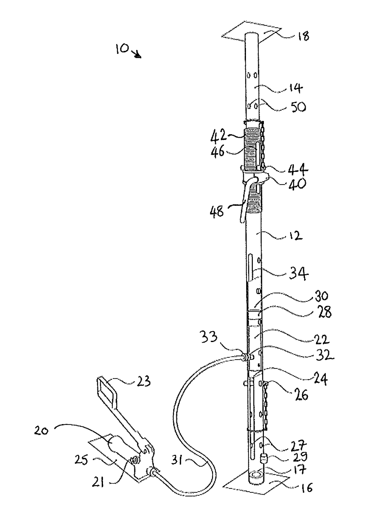
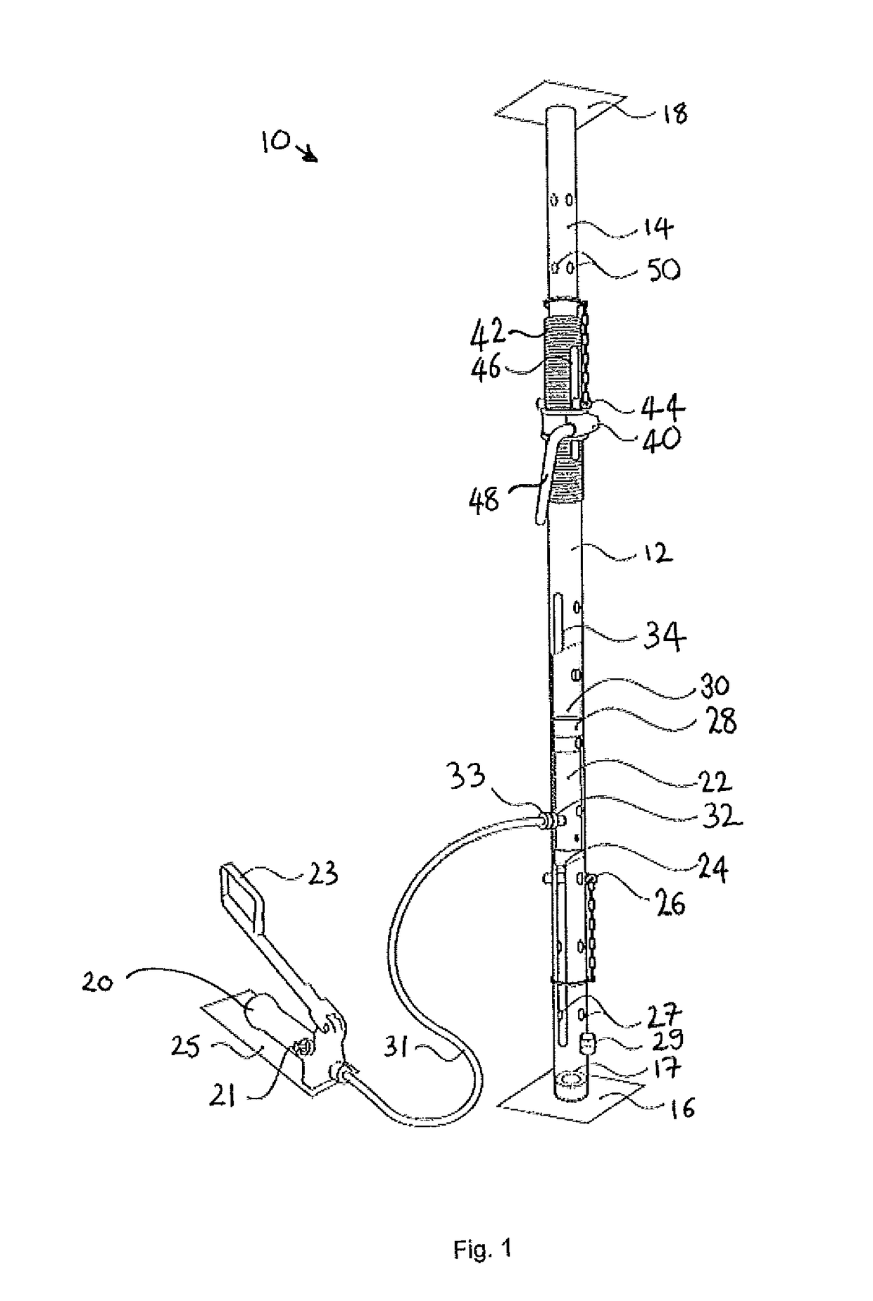
[0128]The present invention relates to a temporary semi-automatic hydraulic load bearing raising and support device for use across a wide variety of industries. The support may also be considered to be one of the following: a temporary Support device / prop, a temporary raising device / prop, a semi-automatic raising and support device, a temporary load bearing lifting and support device / prop or a temporary hydraulic support and lifting device.

[0129]As shown in FIG. 1 and FIG. 2, the support 10 resembles a conventional Acrow prop which may be used for temporarily supporting a load. In particular, the present invention is arranged to support a surface at a static position. For example, the surface may comprise a ceiling / beam / lintel within a structure wherein the usual permanent supports for the ceiling / beam / lintel are being replaced or deemed temporarily insufficient. However, the present invention can be used in numerous situations where a support 10 is required and for which the suppor...


PUM


Abstract

The support 10 of the present invention resembles a conventional Acrow prop which may be used for temporarily supporting a load. In particular, the present invention is arranged to support a surface at a static position. For example, the surface may comprise a ceiling / beam / lintel within a structure wherein the usual permanent supports for the ceiling / beam / lintel are being replaced or deemed temporarily insufficient. However, the present invention can be used in numerous situations where a support 10 is required and for which the support 10 can be quickly and easily installed. The present invention provides (hydraulic) movement means to move the upper end relative to the lower end. In addition, the present invention provides retraction prevention means to prevent the upper end moving towards the lower end whilst supporting the load and prevents the inner core member 14 being forcibly retracted back into the outer sleeve member 12 due to the compressive force of the load. A hydraulic ram 22 has a maximum extension limit and the present invention uses an adjustable mounting / abutment mechanism which means that a relatively small hydraulic ram 22 can be installed in the outer sleeve member 12. This size of hydraulic ram 22 will then be suitable for all heights and the support is not limited to simply being moveable within a restricted range.

Description

FIELD OF THE INVENTION[0001]The present invention relates to a support, an assembly comprising a support and a method of supporting a surface.BACKGROUND TO THE INVENTION[0002]The light construction industry, by way of example, makes use of mechanical, load bearing supports (props), and the most recent and popular versions of which have their origin in a design known as the Acrow. There are now a variety of such products which are available to hire or buy and these are in common use in the building trade around the world.[0003]These mechanical props are limited, however, in terms of how much load may be lifted / supported and it is also well documented that there are considerable health and safety issues during the operation of raising / supporting such loads of varying weights and stresses.[0004]The mining and civil engineering industries make use of elaborate, complex and intricate props which are very costly. Whilst such props may be efficient and safe, they are not simple and quick a...

Claims


Application Information

Patent Timeline
Patent Type & Authority Applications(United States)
IPC IPC(8): E21D15/44E04G23/04E04G25/06
CPCE21D15/44E04G2025/047E04G23/04E04G25/065B66F3/30E04G25/06E21D15/50E04G25/04E21D15/20E21D15/24E21D15/585E04G25/061E04G25/063E21D15/515
Inventor MOYE, THOMAS WRIGLEYMARR, DAVID THOMAS
Owner MMC INNOVATIONS
Why Eureka
Try Eureka