Touch sensing electrode integrally formed with polarizing plate, display device comprising same, and manufacturing method therefor

Inactive Publication Date: 2017-09-28
DONGWOO FINE CHEM CO LTD
View PDF9 Cites 8 Cited by
  • Summary
  • Abstract
  • Description
  • Claims
  • Application Information

AI Technical Summary

Benefits of technology

The present invention is a touch sensing electrode with a polarizing plate that improves visibility and display performances in a foldable display, by reducing reflections and improving anti-reflective properties of both the folded and unfolded parts. The electrode achieves this by forming a slow axis of a retardation film that forms an inclined angle with the folling axis of the display. This ensures that both parts of the display have the same anti-reflective properties, making it easier for users to see and interact with the content.

Problems solved by technology

However, the existing foldable displays (according to the prior art) undergo the decrease of anti-reflective property in the folding part when folded on the folding axis, from which there is a difference of anti-reflective property between the folding part and the unfolding part, making it the visibility of the folding part poor and the overall performance of the displays be deteriorated.

Method used


Image

  • Touch sensing electrode integrally formed with polarizing plate, display device comprising same, and manufacturing method therefor
  • Touch sensing electrode integrally formed with polarizing plate, display device comprising same, and manufacturing method therefor
  • Touch sensing electrode integrally formed with polarizing plate, display device comprising same, and manufacturing method therefor

Examples


example 1

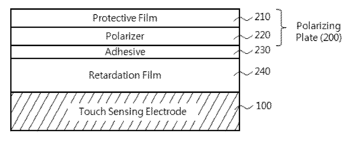
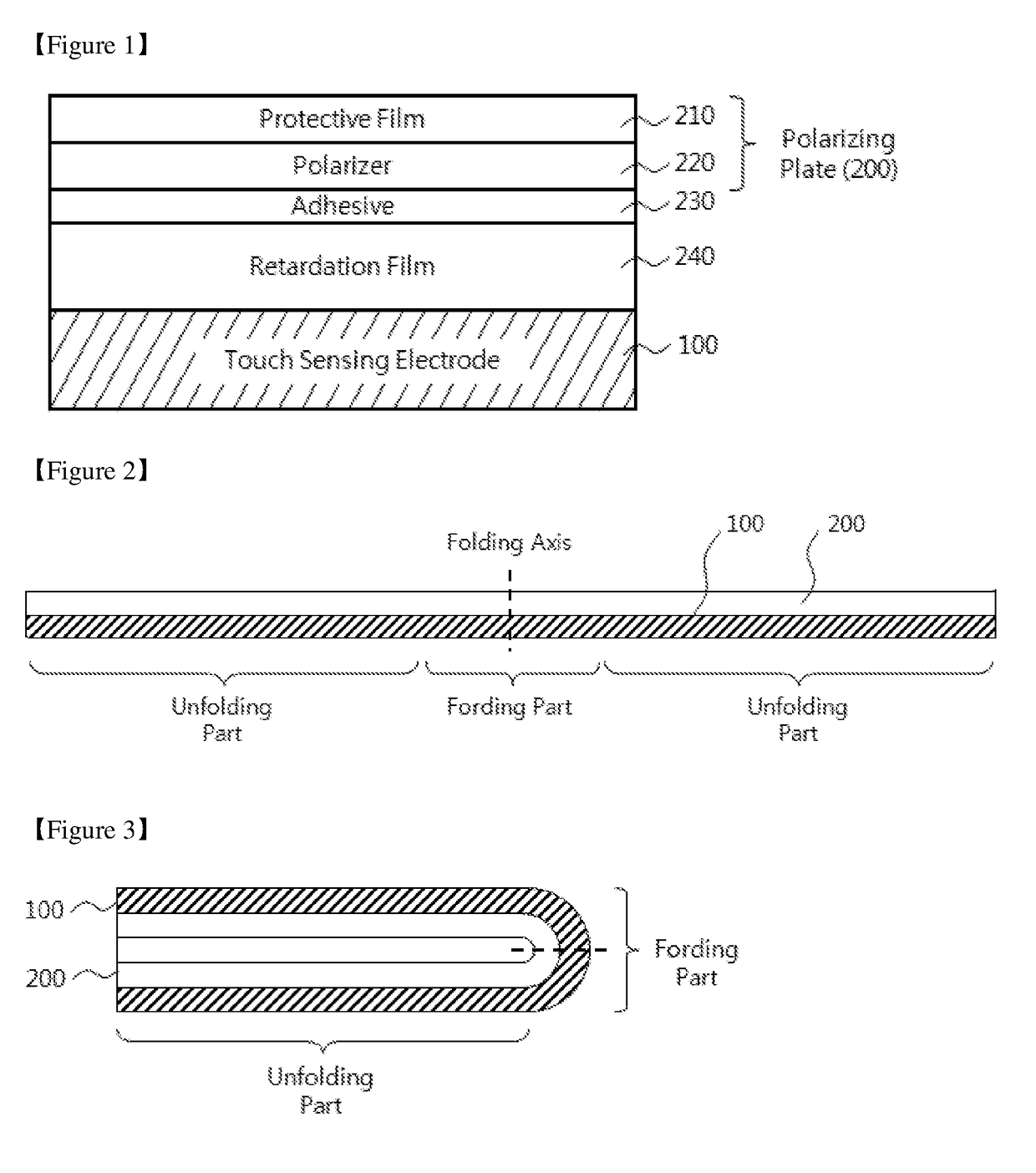
[0050]A retardation film-attached polarizing plate was prepared in the structure shown in FIG. 1, in which a 25 μm-thick triacetyl cellulose film was used as a protective film, a 22 μm-thick polyvinyl alcohol film was used as a polarizer, a 15 μm-thick pressure sensitive adhesive (PSA) film was used as an adhesive, and a 50 μm-thick λ / 4 retardation film (Trade Name: WRS film) having inverse dispersibility was used as a retardation film.

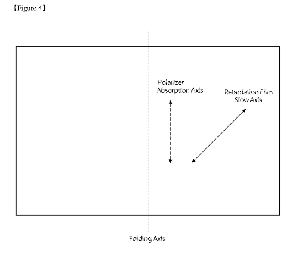
[0051]In the polarizing plate, the absorption axis of the polarizer is parallel with a folding axis and the slow axis of the retardation film forms an inclined angle of 45° with the folding axis (FIG. 4).

example 2

[0052]A retardation film-attached polarizing plate was prepared in the same structure and using the same materials as Example 1, except that the absorption axis of the polarizer is perpendicular to a folding axis and the slow axis of the retardation film forms an inclined angle of 45° with the folding axis (FIG. 5).

experimental example

[0055]The retardation film-attached polarizing plates prepared in Examples 1 and 2 (corresponding to the present invention) and Comparative Examples 1 and 2 were each measured for their front phase differences (Ro) and color difference (ΔEab) between each folding part and each unfolding part, and the results thereof are shown in Table 1.

TABLE 1Gap of PhasePhasePhaseDifferencesColor DifferenceDifference ofDifference ofBetween FoldingBetween FoldingFolding PartUnfolding PartPart and UnfoldingPart and Unfolding(nm)(nm)Part (nm)Part (ΔEab)Example 1141.5146.34.81.6Example 2145.8144.9−0.90.5Comparative96.9145.548.614.7Example 1Comparative176.9148.4−28.59.5Example 2

[0056]From Table 1, it is confirmed that the unfolding parts exhibited equivalent phase difference values for Examples 1 and 2 and Comparative Examples 1 and 2, while the folding parts exhibited a decreased phase difference value when the slow axis of the retardation film is parallel with the folding axis (Comparative Example 1)...


PUM


Abstract

The present invention relates to a touch sensing electrode with a polarizing plate, a display device comprising the same, and a method for fabricating the same.The touch sensing electrode with a polarizing plate according to the present invention comprises a touch sensing electrode capable of being folded and unfolded on its folding axis; a retardation film disposed on the touch sensing electrode and having a slow axis that forms an inclined angle with the folding axis; and a polarizing plate disposed on the retardation film.

Description

TECHNICAL FIELD[0001]The present invention relates to a touch sensing electrode with a polarizing plate, a display device comprising the same, and a method for fabricating the same. More particularly, the present invention relates to a touch sensing electrode with a polarizing plate, which can be applied in a flexible display or a foldable display, a display device comprising the same, and a method for fabricating the same.BACKGROUND ART[0002]Recently, with the rapid growth of semiconductor technology, there are dramatically increasing demands on display device to reduce their size and weight and to have good performance.[0003]Also, various kinds of electronic displays have been developed for the visual delivery of information in information-oriented society, and portable displays are gaining attention with the development of mobile communications technology.[0004]Such a display device has been changed from a cathode ray tube (CRT) to a liquid crystal display (LCD), a plasma display...

Claims


Application Information

Patent Timeline
IPC IPC(8): G06F3/041G02B5/30
CPCG06F3/041G06F2203/04103G06F2203/04102G02B5/3083G02F1/13338G02F1/133528G02F1/13363G02B5/3016G06F3/0443G02B5/30
Inventor LEE, JAEHYUNCHOI, BYUNG JINPARK, DONG PILSEO, YONG WONSONG, BYUNG HOON
Owner DONGWOO FINE CHEM CO LTD
Why Eureka
Try Eureka