

Charging device, charging system, and electronic apparatus
a charging device and charging system technology, applied in the direction of magnetic/electric field screening, transportation and packaging, and battery arrangement, can solve the problem of difficulty in reducing the overall size of the device, and achieve the effect of reducing the size of the charging devi
- Summary
- Abstract
- Description
- Claims
- Application Information
AI Technical Summary
Benefits of technology
Problems solved by technology
Method used
Image

Examples
first embodiment
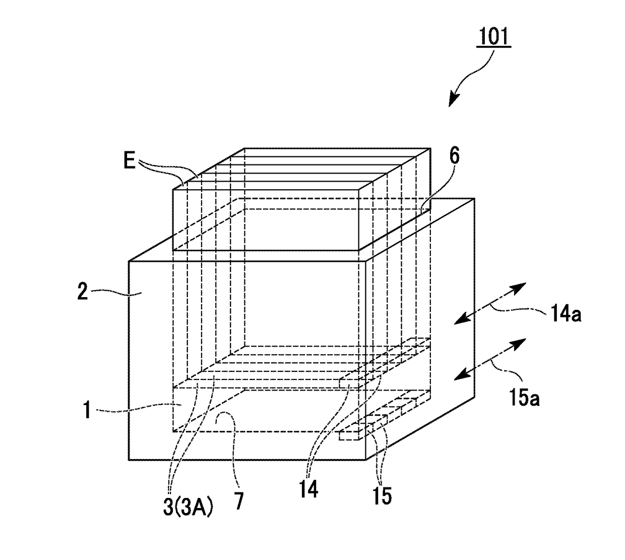
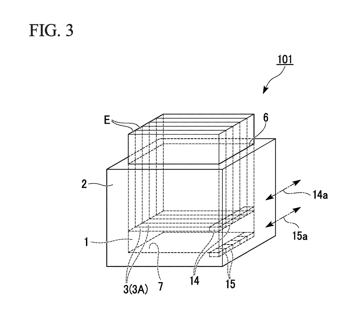
[0034]A charging device 101 according to a first embodiment of the present invention will be described with reference to FIGS. 2 to 7.
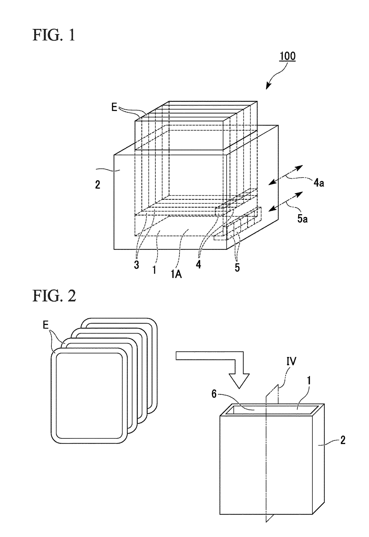
[0035]In these figures, FIGS. 2 to 5 show a more specific charging device 101 than FIG. 1, and a plurality of plate-like electronic apparatuses E are stored in a piled-up state in the storage space 1 of the charging box 2.
[0036]The electronic apparatus E is a display terminal formed in a plate shape, and is, for example, a flexible display device used as electronic paper, or the like.
[0037]The storage space 1 of the charging box 2 is disposed vertically. The storage space 1 is in a bottomed shape in which an opening 6 is formed at an upper portion of the charging box 2 and a bottom 7 is formed at a lower portion. The charging device 101 has the opening 6 at the upper portion through which the plurality of electronic apparatuses E are put in and taken out from the storage space 1 of the charging box 2.
[0038]Here, the plurality of electronic apparatuses...
second embodiment
[0055]A charging device 101′ according to a second embodiment of the present invention will be described with reference to FIGS. 9 and 10.
[0056]The charging device 101′ according to the second embodiment differs from the charging device 101 according to the first embodiment in installation positions of power-receiving coils 14′ provided on an electronic apparatus E and power-supplying coils 15′ provided on a charging box 2.
[0057]Specifically, as shown in FIGS. 9 and 10, the power-supplying coils 15′ of the second embodiment are provided on an inner surface of the charging box 2 serving as a side wall portion 8 of the storage space 1, and are disposed in an arrangement direction 15a′ in which electronic apparatuses E are arranged.
[0058]Correspondingly, when a plurality of electronic apparatuses E are stored side by side in the storage space 1, each of the power-receiving coils 14′ provided at side end portions 3 (3B) of the electronic apparatuses E is disposed to face one of the powe...
third embodiment
[0064]A charging device 102 according to a third embodiment of the present invention will be described with reference to FIGS. 11 to 13.
[0065]As shown in FIGS. 11 and 12, the charging device 102 according to the third embodiment differs from the charging devices 101 and 101′ according to the first and second embodiments in an arrangement state of the electronic apparatuses E in storage space and provision of a guide mechanism which guides the electronic apparatuses E.
[0066]Specifically, a charging box indicated by a reference numeral 20 includes an upper opening 21 serving as an entrance for putting the electronic apparatuses E in, a lower opening 22 provided below the upper opening 21 and serving as an exit for taking the electronic apparatuses E out, and a guide mechanism 24 for guiding the electronic apparatuses E to a storage space 23 inside the charging box 20 from the upper opening 21.
[0067]In the storage space 23 of the charging box 20, a plurality of electronic apparatuses E...
PUM
 Abstract
Description
Claims
Application Information