Earphone device having concentrating tube

a technology of concentrating tube and earphone, which is applied in the direction of transducer details, earpiece/earphone attachment, electrical transducer, etc., can solve the problems of increased earphone size, unclear output sound, and difficult to produce clear sound by single diaphragm

Inactive Publication Date: 2017-09-28
JETVOX ACOUSTIC
View PDF18 Cites 19 Cited by
  • Summary
  • Abstract
  • Description
  • Claims
  • Application Information

AI Technical Summary

Benefits of technology

[0017]According to the above embodiments, the earphone device having a concentrating tube comprises the concentrating tube, the active diaphragm, and the passive diaphragm. The earphone device is suitable for use in terms of size because only one diaphragm is added, and two moving coil drivers are not required. In addition, a gas flow generated by the active diaphragm is gathered by the concentrating tube and then pushes and vibrates the passive diaphragm. A gas flow generated by the passive diaphragm returns through the concentrating tube to push the active diaphragm and also transmits acoustic waves produced by the passive diaphragm; consequently, the acoustic waves of the passive diaphragm reinforces a part of frequency of sound which is unclear in the situation that the sound is only generated by the active diaphragm. Meanwhile, since the gas flow pushes the active diaphragm, the amplitude of vibration of the active diaphragm is increased to reach a frequency raising effect.

Problems solved by technology

According to prior techniques, the parts of low frequency and the high frequency are processed by electro-acoustic conversions through the single diaphragm; however, it is hard to produce clear sound by the single diaphragm due to different characteristics of frequency response.
Distortion may occur during the electro-acoustic conversions, which results in outputted sound being unclear.
Although two moving coil drivers can be adopted in an earphone to resolve the issue by having the two drivers respectively generate acoustic waves of high frequency and low frequency via a frequency dividing circuit, this increases the size of the earphone, making it unsuitable for use.
In addition, the pressure of gas inside the earphone directly affects the vibration of the diaphragm and consequently affects the frequency response thereof.
As a result, certain frequency range(s) of sound that the earphone should generate, is lost.

Method used


Image

  • Earphone device having concentrating tube
  • Earphone device having concentrating tube
  • Earphone device having concentrating tube

Examples


Embodiment Construction

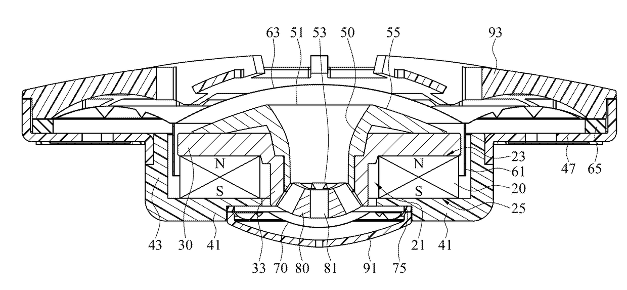
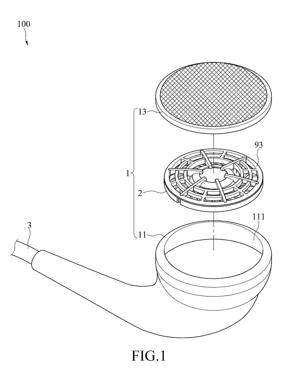
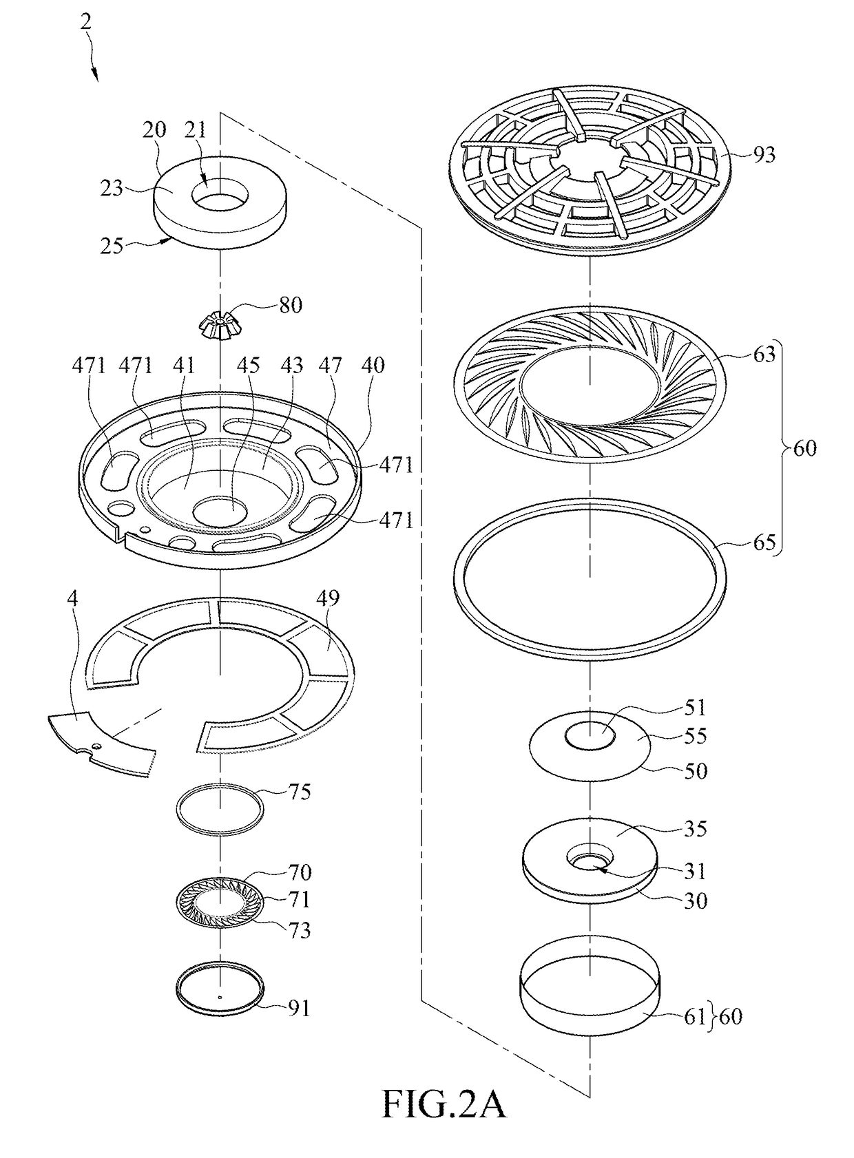
[0025]Please refer to FIGS. 1, 2A, 2B, and 3, in which FIGS. 1, 2A, 2B, and 3 are respectively a partial exploded view of an earphone device having a concentrating tube, an exploded view in a viewing angle of the earphone device, an exploded view in another viewing angle of the earphone device, and a cross sectional view of the earphone device according to an embodiment of the instant disclosure. As shown in FIGS. 1, 2A, 2B, and 3, the earphone device 100 comprises an annular magnet 20, a first yoke 30, a second yoke 40, a concentrating tube 50, a speaker assembly 60, and a passive diaphragm 70. The annular magnet 20, the first yoke 30, the second yoke 40, the concentrating tube 50, the speaker assembly 60, and the passive diaphragm 70 can be assembled to each other into a speaker driver 2, which is received in a receiving space 111 of a body 11 of an earphone housing 1 and protected by a cover 13.

[0026]The annular magnet 20 comprises a central through hole 21, a first magnetic pole...


PUM


Abstract

An earphone device having a concentrating tube includes an annular magnet, a first yoke, a second yoke, a concentrating tube, a speaker assembly, and a passive diaphragm. The first and second yokes are respectively connected to first and second magnetic pole faces of the annular magnet. The concentrating tube is received in a central through hole of the annular magnet. The concentrating tube includes first and second open ends. The speaker assembly includes a voice coil and an active diaphragm. The passive and active diaphragms are at two opposite ends of the concentrating tube. The active and passive diaphragms are respectively close to the first and second open ends. A gas flow generated by the active diaphragm is gathered by the concentrating tube and pushes the passive diaphragm. A gas flow generated by the passive diaphragm returns through the concentrating tube to push the active diaphragm and transmits acoustic waves.

Description

CROSS-REFERENCE TO RELATED APPLICATION[0001]This non-provisional application claims priority under 35 U.S.C. §119(a) to Patent Application No. 105204256 filed in Taiwan, R.O.C. on Mar. 25, 2016, the entire contents of which are hereby incorporated by reference.BACKGROUND[0002]Technical Field[0003]The instant disclosure relates to a field of earphone and, more particularly, to an earphone device having a concentrating tube.[0004]Related Art[0005]Conventional earphones perform electro-acoustic conversions by moving coil drivers. The moving coil driver includes a voice coil, a permanent magnet, and a diaphragm. When audio signals are transmitted to the voice coil by an audio line, the voice coil generates a magnetic field based upon electromagnetic induction. The diaphragm is vibrated by the interaction of the magnetic field generated by the electromagnetic induction and the magnetic field generated by the permanent magnet, and the audio signals are converted into acoustic waves for ou...

Claims


Application Information

Patent Timeline
Patent Type & Authority Applications(United States)
IPC IPC(8): H04R1/10H04R1/28H04R1/34H04R9/06
CPCH04R1/1075H04R1/345H04R1/2834H04R9/06H04R1/1016H04R1/2857H04R7/02H04R9/025H04R9/04
Inventor HUANG, TO-TENG
Owner JETVOX ACOUSTIC
Why Eureka
Try Eureka