
Methods, systems, apparatuses, and computer programs for processing tomographic images

a technology of tomographic images and computer programs, applied in the field of tomographic images, can solve the problems of reducing the diagnostic usefulness of projection images, too large for chair-side imaging, and high cost of ownership of machines

Active Publication Date: 2017-10-05
SIRONA DENTAL
View PDF6 Cites 42 Cited by
  • Summary
  • Abstract
  • Description
  • Claims
  • Application Information

AI Technical Summary

Benefits of technology

This patent describes methods, systems, apparatuses, and computer programs for processing tomographic images. These techniques can identify a specific tomographic image from a group of images based on information specifying a region of interest in the image. The identified image will be in greater focus in the area corresponding to the region of interest than other images. This enhances the ability to generate clinical information from multiple projection images. Overall, the patent aims to improve the efficiency and accuracy of tomographic image processing for medical applications.

Problems solved by technology

However, from such a two-dimensional projection image it cannot be determined that there were two blocks of material (6002 and 6004) at different positions in the path of Ray A, as opposed to a single block of material which caused the same amount of x-ray attenuation.
As such, overlapping objects may easily obscure one another and reduce the diagnostic usefulness of the projection image.
While CT and CBCT machines may produce a stack of parallel 2D tomographic image slices, these machines carry a high cost of ownership, may be too large for use in chair-side imaging, and expose patients to a relatively high dose of x-rays.
Clinicians locate features of interest within the patient's anatomy by evaluating image slices one at a time, either by manually flipping through sequential slices or by viewing the image slices as a cine loop, which are time-consuming processes.
It may also be difficult to visually grasp aspects of anatomy in a proper or useful context from the two-dimensional images.
Quality may be affected by image artifacts.
Tomosynthesis datasets typically have less information than full CBCT imaging datasets due to the smaller scan angle, which may introduce distortions into the image slices in the form of artifacts.
For example, intraoral tomosynthesis imaging can exhibit significant artifacts because structures within the oral cavity are generally dense and radiopaque.
Still further, spatial instability in the geometry of the tomosynthesis system and / or the object can result in misaligned projection images which can degrade the quality and spatial resolution of the reconstructed tomosynthesis image slices.
Spatial instability may arise from intentional or unintentional motion of the patient, the x-ray source, the x-ray detector, or a combination thereof.

Method used


Image

  • Methods, systems, apparatuses, and computer programs for processing tomographic images
  • Methods, systems, apparatuses, and computer programs for processing tomographic images
  • Methods, systems, apparatuses, and computer programs for processing tomographic images

Examples


Embodiment Construction

[0104]In accordance with example aspects described herein, methods, systems, apparatuses, and computer programs are provided for generating clinical information from a tomographic dataset, and more particularly, for identifying within an intraoral tomosynthesis dataset high-focus images containing features of interest.

Tomosynthesis System

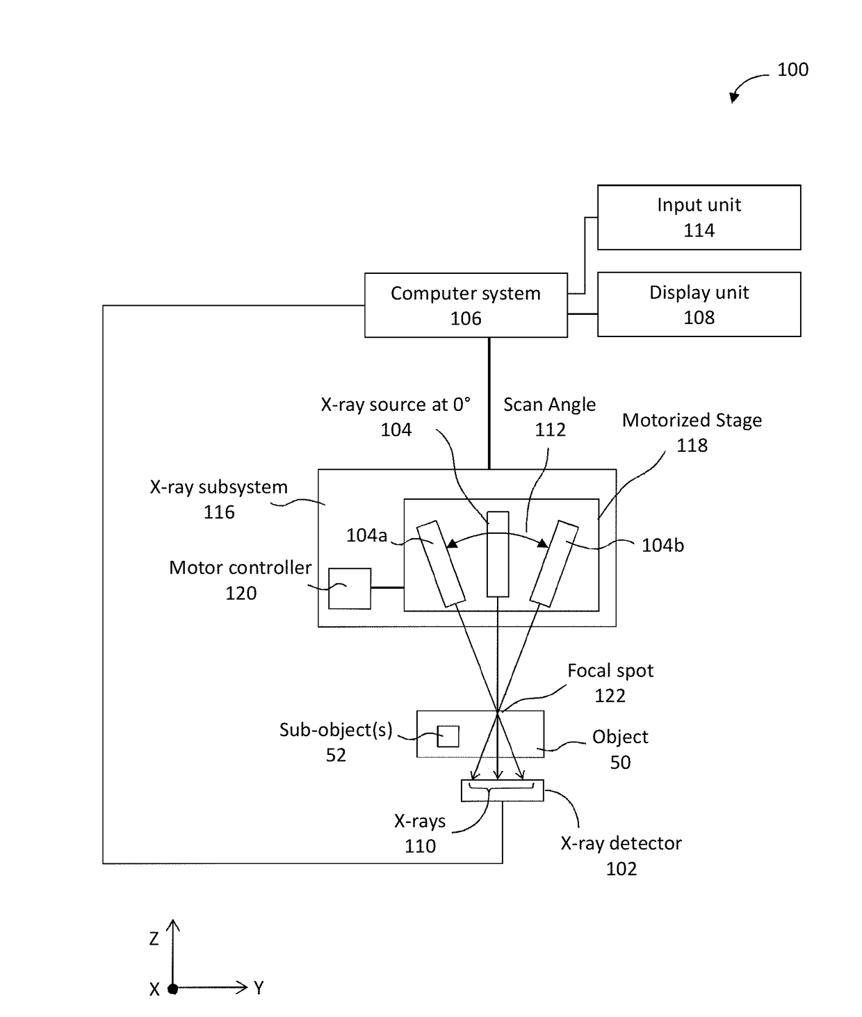
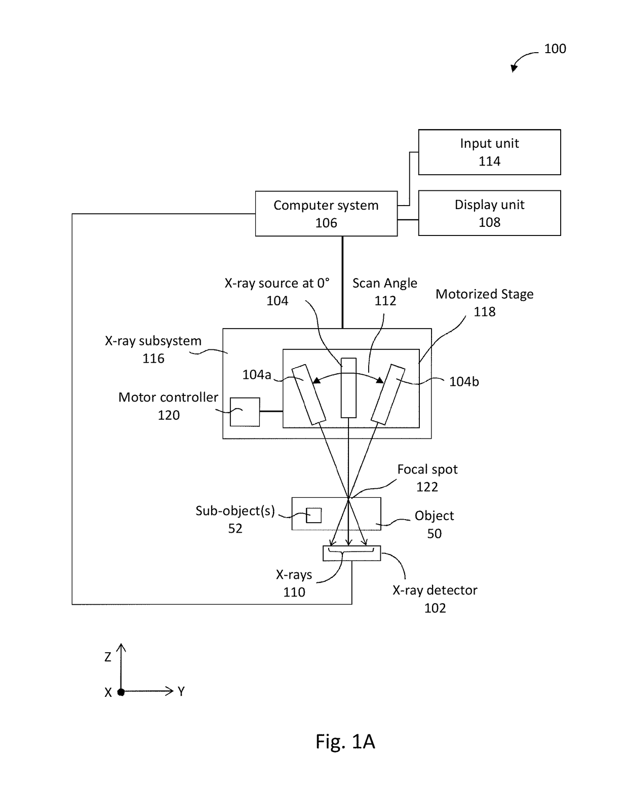
[0105]FIG. 1A illustrates a block diagram of an intraoral tomosynthesis system 100 for obtaining an intraoral tomosynthesis dataset, and which is constructed and operated in accordance with at least one example embodiment herein. The system 100 can be operated to obtain one or more x-ray images of an object 50 of interest, which may further include one or more sub-object(s) 52. For example, object 50 may be a tooth (or teeth) and surrounding dentition of a patient, and sub-object(s) 52 may be root structures within the tooth.

[0106]The system 100 includes an x-ray detector 102 and an x-ray subsystem 116, both of which, including subcomponents thereof...


PUM


Abstract

A method, apparatus, system, and computer program for generating clinical information. Information indicating at least one clinical aspect of an object is received. Clinical information of interest relating to the at least one clinical aspect is generated from a plurality of projection images.

Description

CROSS-REFERENCE TO RELATED APPLICATIONS[0001]This application claims priority to U.S. Provisional Patent Appln. Nos. 62 / 050,881, filed Sep. 16, 2014, 62 / 076,216, filed Nov. 6, 2014, and 62 / 214,830, filed Sep. 4, 2015, the contents of which are incorporated by reference herein in their entirety.BACKGROUNDField[0002]The present application relates generally to obtaining tomographic images in a dental environment, and, more particularly, to methods, systems, apparatuses, and computer programs for processing tomographic images.Description of Related Art[0003]X-ray radiography can be performed by positioning an x-ray source on one side of an object (e.g., a patient or a portion thereof) and causing the x-ray source to emit x-rays through the object and toward an x-ray detector (e.g., radiographic film, an electronic digital detector, or a photostimulable phosphor plate) located on the other side of the object. As the x-rays pass through the object from the x-ray source, their energies ar...

Claims


Application Information

Patent Timeline
IPC IPC(8): A61B6/00A61B6/02A61B6/14
CPCA61B6/5217A61B6/463A61B6/025A61B6/14A61B6/04A61B6/467A61B6/5211A61B6/5223A61B6/4085A61B6/466A61B6/469A61B6/5205A61B6/5235A61B6/5258A61B6/5264A61B6/027G16H50/30G16H50/20G06T19/00G06T2219/008G06T2207/10116G06T2207/10081G06T7/0002G06T2207/30168G06T11/008A61B6/586A61B6/58A61B6/512A61B6/51G06T5/73A61B6/5276A61B6/584A61B6/582G06T7/0014G06T7/181G06T7/12G06T7/136G06T7/143G06T7/149G06T2207/20116G06T11/005G06T7/248G06T7/254G06T7/60G06T5/94
Inventor MANDELKERN, STANLASKER, JOSEPHDUEWER, FRED
Owner SIRONA DENTAL
Learn More