Method and device for nasal dilation by applying force to a target cheek area without mandibular displacement

Inactive Publication Date: 2017-10-05
VIKEN JAMES P
View PDF3 Cites 2 Cited by
  • Summary
  • Abstract
  • Description
  • Claims
  • Application Information

AI Technical Summary

Benefits of technology

[0015]An important object of the nasal dilation device is to increase the responsiveness of the automatic self-adjusting PAP device's control systems to allow a lower air delivery pressure setting than otherwise might be possible. This can help to increase patient comfort if the pressure can be somewhat reduced while still being adequate to prevent the occurrence of OSA or other sleep disorder events. It is known in the art that the higher the air delivery pressure by the PAP device, the greater the tendency for air to leak around the mask, whether it be a nose only mask, a full face mask or a hybrid form of the two. When air leaks occur due to higher air delivery pressures being used, then the solution typically is the tightening of the straps or headgear used to hold the mask type device securely to the face. It is known that tightening of the straps can decrease patient comfort in some cases.
[0016]During the use of a PAP type device, holding the air delivery pressure down to the lowest possible level while still high enough to prevent the occurrence of OSA is an important consideration for PAP and mask device designers. Air leaks through the mask device, which typically occur at the edge seals of the full face type masks, can generate annoying noise which can wake the patient or his or her sleeping partner. When using an automatic self-adjusting PAP type device, these air leaks through the edge seals of the mask will typically cause the device to automatically self-adjust to a higher air delivery pressure output to compensate for the leakage and pressure reduction. The use of the nasal dilation device can result in a barrier provided against the side seals of the full face mask and can help prevent these unwanted air leaks which can be annoying and cause an unwanted increase in the pressure output of the PAP type device.
[0017]Therefore, another important object of the use of this invention i

Problems solved by technology

Rather counterintuitively, an inwardly directed force applied at a target area between the user'

Method used


Image

  • Method and device for nasal dilation by applying force to a target cheek area without mandibular displacement
  • Method and device for nasal dilation by applying force to a target cheek area without mandibular displacement
  • Method and device for nasal dilation by applying force to a target cheek area without mandibular displacement

Examples


Example

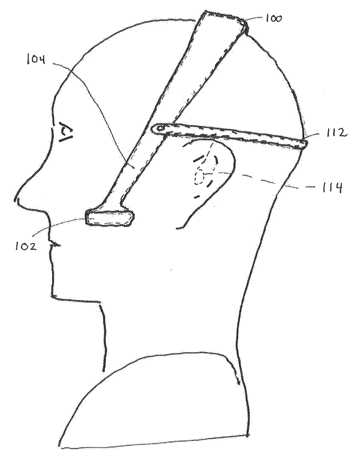
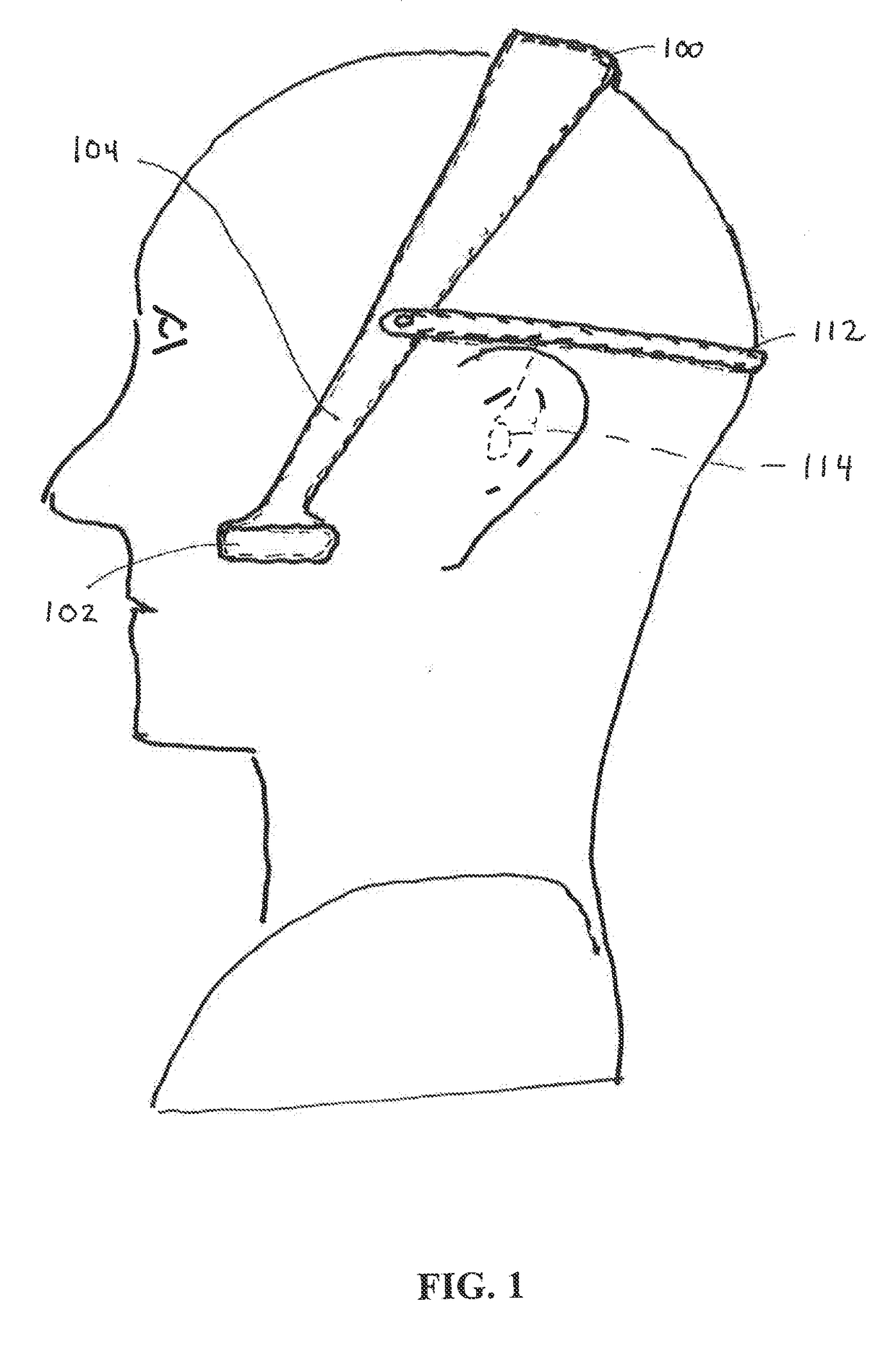
[0033]FIG. 1 depicts another embodiment of the invention in a free standing, yoke supported form, identified as nasal dilation device 100. Nasal dilation device 100 is a free standing unit including a spring yoke 104 for support and placement of a pair of affixed pads 102.

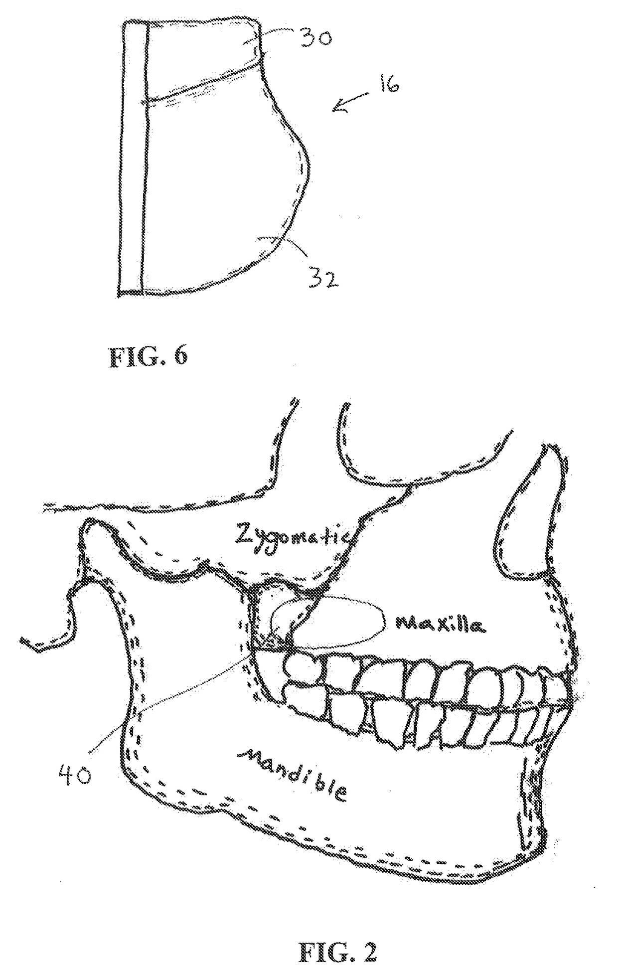
[0034]Referring to FIG. 2, the target area is defined as region 40, generally that part of the cheek where the lower lateral pterygoid process bone intersects with a maxilla bone and a zygomatic bone (also called the zygomatic arch or cheek bone). The target area 40 is preferably centered between the zygomatic bone and the upper teeth. The infratemporal surface of the maxilla is contained in the target area 40. The posterior superior alveolar nerves cross through the target area 40. The nasal dilation devices of the present invention preferably provide a force of between about 0.5 lbs-f to 3 lbs-f to the target areas 40 on each side of the user's head. Forces in the range of about 0.05-1.5 lbs-f are delivered to th...


PUM


Abstract

A nasal dilation device and method of use for depressing targeted areas of cheek tissue providing for enhanced inhalation and exhalation via dilation of nasal passageways away from the targeted areas. The device may be used to enhance respiration during a variety of activities, and is especially beneficial during the use of positive airway pressure (PAP) type medical devices. The device may include pads adapted to engage target areas of a user's cheek and to maintain cheek tissue against a bone surface during inhalation and exhalation. The device includes a support element coupled to the pads to maintain the pads at the targeted areas during use.

Description

RELATED APPLICATIONS[0001]This application claims the benefit of U.S. application Ser. No. 14 / 070,910, filed Nov. 4, 2013, which claimed the benefit of U.S. application Ser. No. 12 / 945,826, filed Nov. 12, 2010, which claimed the benefit of U.S. Provisional Application No. 61 / 260,682, filed Nov. 12, 2009, and each application being incorporated herein by reference.FIELD OF THE INVENTION[0002]This invention generally relates to a user interface device and more particularly to a device for enhancing respiration during various user activities via nasal passage dilation.BACKGROUND OF THE INVENTION[0003]The prior art is replete with efforts to control snoring and sleep apnea. Among the less intrusive methods of preventing snoring are special pillows, nasal strips, wrist alarms and chemical sprays. Shaped pillows have been designed to realign the back and spine and to relieve muscle stress during sleep, while the adhesive nasal strips hold open the nostrils of a sleeper to improve breathin...

Claims


Application Information

Patent Timeline
IPC IPC(8): A61F5/08
CPCA61F5/08A61F5/56A61M16/0683A61M2016/0661A61M2210/0637A61M16/0605A61M16/0688
Inventor VIKEN, JAMES P.
Owner VIKEN JAMES P
Why Eureka
Try Eureka