V-type filter frame
- Summary
- Abstract
- Description
- Claims
- Application Information
AI Technical Summary
Benefits of technology
Problems solved by technology
Method used
Image

Examples
Embodiment Construction
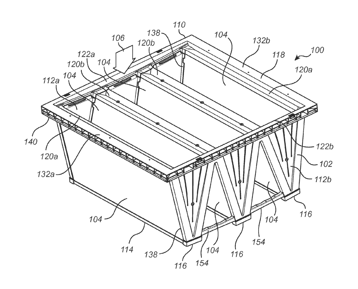
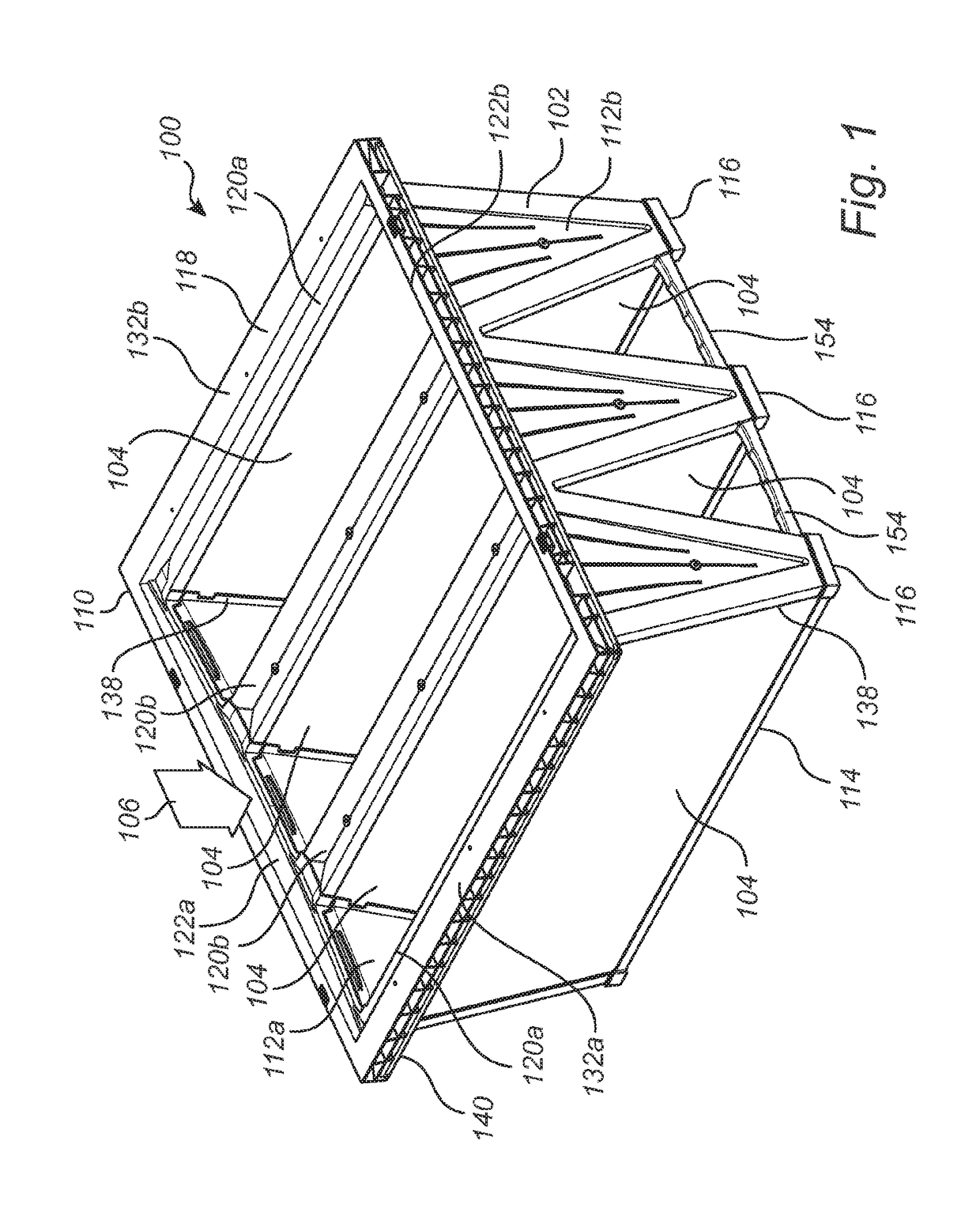
[0039]According to an embodiment of the filter assembly 100, shown in FIG. 1, it comprises an embodiment of the filter frame 102, and several, in this embodiment six, media packs 104 carried by the filter frame 102. Although the invention will be described with reference to a 3V embodiment, it is understood that the invention is equally applicable to 1V, 2V, 4V or more V configurations, i.e. filter assemblies comprising 2, 4, 8, or more filter media packs. The media packs 104 can be of any suitable kind, but typically each media pack 104 comprises a sheet of filter media, which has been pleated to an accordion shape in order to increase the effective filtering area of the filter body. Although the filter is shown having pleated filter media packs, it is contemplated that the filter media packs may be comprised of carbon beds or other gas phase filter medium. The filter media pack 104 may be suitable for at least one of liquid phase, gas phase, particulate or molecular filtration. In...
PUM
| Property | Measurement | Unit |
|---|---|---|
| Digital information | aaaaa | aaaaa |
Abstract
Description
Claims
Application Information
 - R&D
- Intellectual Property
- Life Sciences
- Materials
- Tech Scout
- Unparalleled Data Quality
- Higher Quality Content
- 60% Fewer Hallucinations
Browse by: Latest US Patents, China's latest patents, Technical Efficacy Thesaurus, Application Domain, Technology Topic, Popular Technical Reports.
© 2025 PatSnap. All rights reserved.Legal|Privacy policy|Modern Slavery Act Transparency Statement|Sitemap|About US| Contact US: help@patsnap.com